Atti's successful ZPM replication

  • 3.8K Views
  • Last Post 27 November 2023
  • Topic Is Solved
Atti posted this 25 November 2022

Hi everyone.

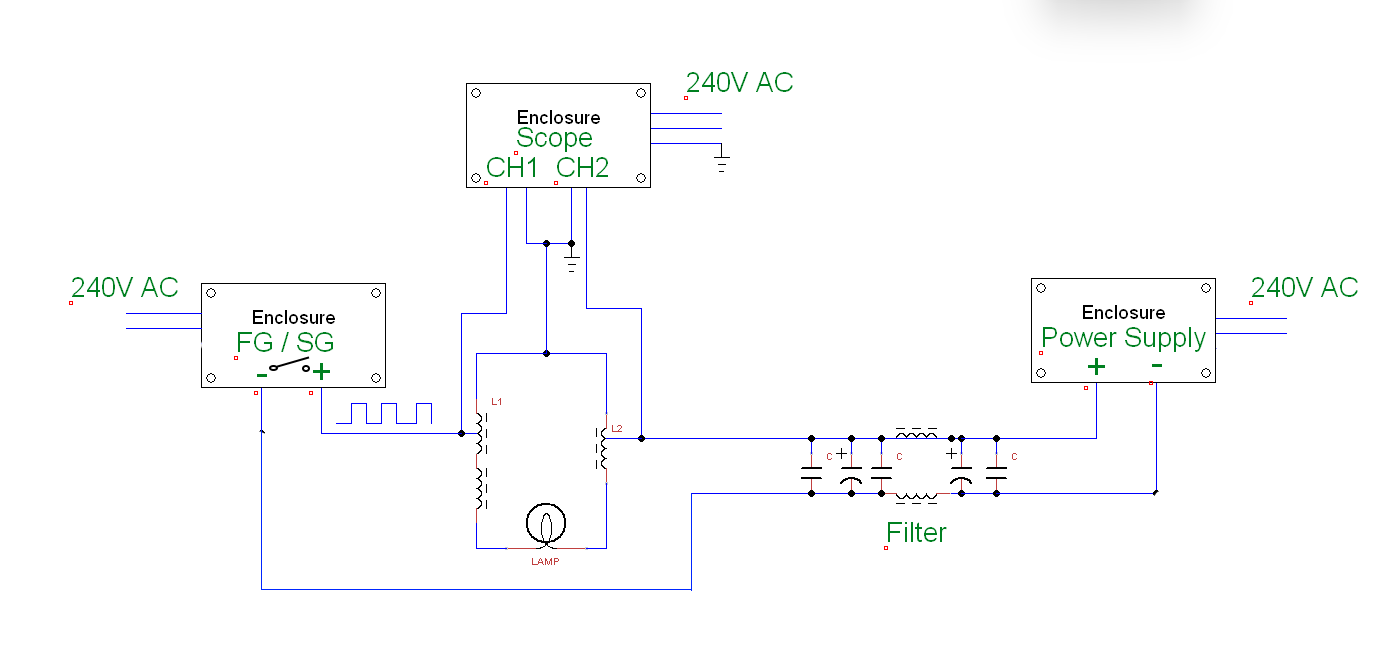
I just wanted to look at a few things in this simple compilation. As you can see, it's almost the same drawing as the one that Fighter gave us. I played with it a bit.
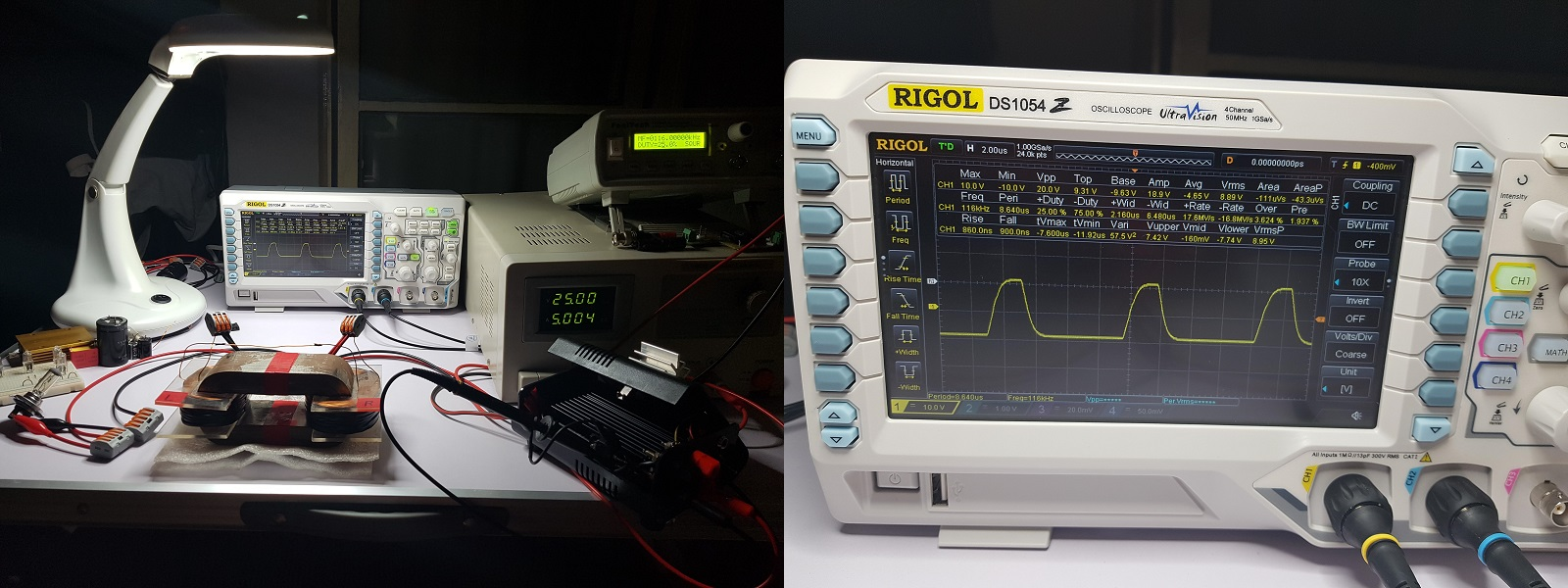
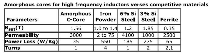
The core is a tiny Amcc20. Frequency between 90-110Khz. Filling factor 50%. Supply voltage between 20-30 volts. The power supply L-C filter works well. Roll ratio 1:2

Changes caused by parasitic capacitances are inevitable at such a high frequency. You can see them in the two videos. Sometimes the power is increased and sometimes the current is reduced.
Grounding can help in some cases. But the influencing factor must be taken into account during the measurements. It only has an effect above a certain frequency.
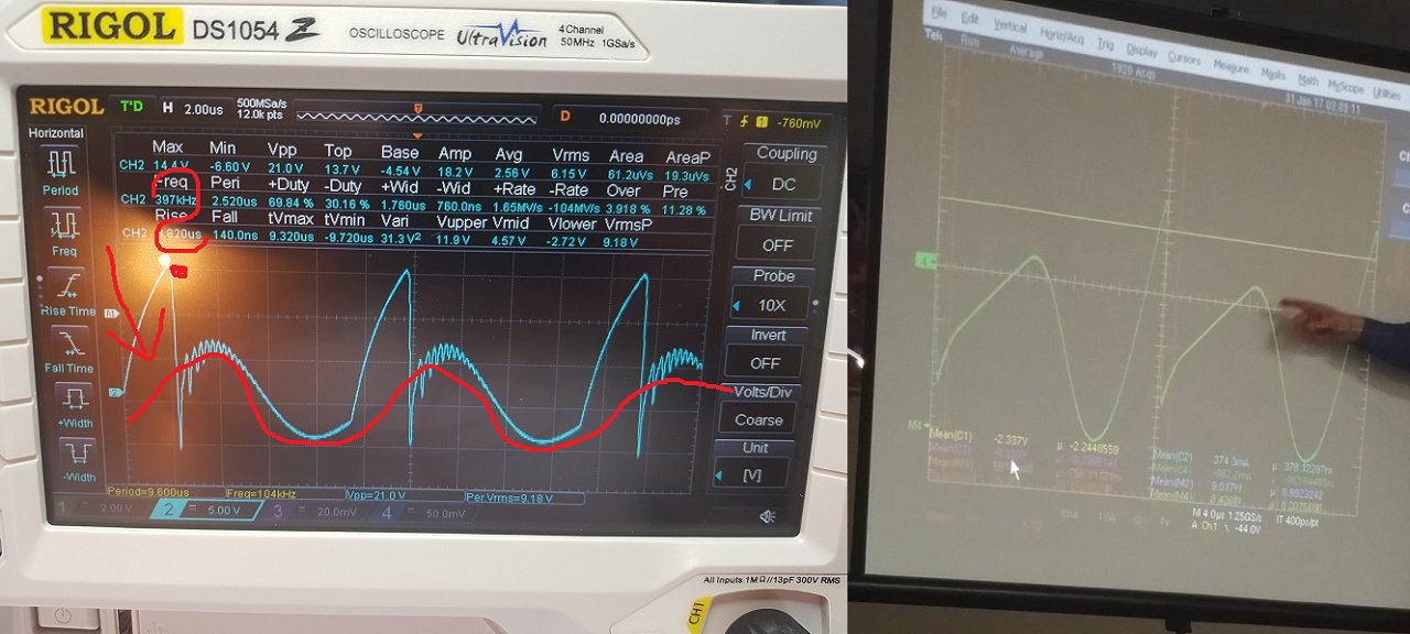
This is just for information, but as you can see, there are cases when the current drawn from the power supply is close to zero. There are times when grounding is necessary.

In this oscilloscope examination, I was curious as to where and how the two coils resonate. Or how I see it. Or is it visible at all.

When the current drawn from the power supply is the lowest, the CH2 (blue) channel is at a higher voltage. But this is the coil with less turns. Thus, it should be smaller by default (or at a lower frequency). So when this coil is at a higher voltage, it works on the other coil and charges back to the power supply. (here I deliberately did not say L1 or L2 because only the principle is the point, but this still awaits further investigation)
In some cases, the hump characteristic of parametric excitation can also be observed in the measured signal. Vidura alluded to this in one of his comments.
I have not done the loading according to Fighter or YoElMiCrO. The change is not so spectacular for the load.

It would definitely be necessary to use an iron core with a larger volume and a coil with a larger surface area.
This experiment was just for information on my part. To be continued later.

@Itsu.

As you can see, the current can be reduced to almost zero. Probably also with higher loads. The generator effect can prevail. But there are a lot of questions for me right now.

Atti.


Atti posted this 28 November 2022

Itsu.


I have attached the drawing in video form (so it's easier). So grounding is not connected to anything. Only the oscilloscope receives the mains ground. The power supply (or maybe battery) is not grounded. The H-bridge controller is not connected to mains ground. It only takes one impulse, that's the point. This could be done with a 555 timer or an opto-isolated drive. Or as you use it in the first drawing you provided.
I used this because it's handy.
Thanks.
Atti.

Itsu posted this 29 November 2022


Atti,

thanks, i have removed the grounds from the FG/SG and PS and connected the minus/return from the PS and FG/SG.
So the connections should be like this:

Itsu 

Atti posted this 03 December 2022

According to the specified parameters, I tried the connections with several ferrites and transformer iron.

I also replaced the control circuit (Tl494 control-Tc4429 fet drive) The gate signal was not distorted. The result is the same, so the phenomenon is not only with the H bridge drive.

At the moment, it is a question for me why only the Amcc core behaves this way the best. It also works with a CRT line diverter ferrite, but it is not so spectacular.
 As you can see, when the earth is placed at a certain point, the neon lamp lights up everywhere. In this case, the parasitic capacitance affects the current drawn from the power supply. That is, it decreases.
However, in this case, the Fet heats up a little. If the neon lamp is not lit, there is no heating. So this is one of the signs to look for.

Also, I have a question (and this is probably the second setting to look for, or the one I uploaded in the Cap1 video at 0:22) of the wavyness in the Fighter setting.


At first I thought the Fighter's distorted mosfet gate signal was causing the problem.
But now with the use of the new control, I could see that this should not be a problem. In other words, no one has to find fault in the control. A ground loop is not possible, this should not be a problem either.
Larger volume Amcc core with higher inductance can give better results.
Unfortunately, I currently have no way to test the settings with such a core.

Atti.

Fighter posted this 03 December 2022

Hi Atti,

Thanks for sharing your tests and your conclusions !

There was a problem with the images you tried to add in your post, they appear to be broken.

If you actually wanted to show your Cap1 video starting at 0:22, I fixed it for you.

If you wanted to add also images you can edit the post and insert the images by uploading them.

Regards,

Fighter

"If you want to find the secrets of the universe, think in terms of energy, frequency and vibration."
Nikola Tesla
Atti posted this 03 December 2022

Thanks for the edit.

Fighter posted this 03 December 2022

Absolutely no problem, you're welcome !

"If you want to find the secrets of the universe, think in terms of energy, frequency and vibration."
Nikola Tesla
Jagau posted this 03 December 2022

Remember that the saturation point of a standard ferrite is around 0.35 Tesla and the AMCC core saturates at 1.56 Tesla, there is a large margin before reaching saturation for the AMCC type core .

in addition to having better permeability

Jagau

editor posted this 03 December 2022

Hi Atti,

great stuff... congrats on the experiment.

Is it possible to do another try without the scope connected and not use any mains power?

regards, e

Atti posted this 04 December 2022

Hi editor.


As you could see in the video. If the scope is not connected, the neon light does not light up.

In this setting. It could be another phenomenon.


Atti.

Atti posted this 09 December 2022

We have already seen this whole layout in several applications.
Notice the applications. LET'S REPLACE IT!
Consider the DC offset during the measurement test.

  Let's examine the connection based on the figure. It is a DC motor.
But we can also examine the operation of the MPPT charge controller used in photovoltaic systems.


Here is a simple orientation with the oscilloscope:  


In the case of a transformer, at 6:10.  


Here you can see how the current of the swing diode develops. There are times when it is higher than the current drawn by the power supply. How can this be and what does it result in? Notice the process.

-Let Ua battery voltage be 10V.
- Assume that the Ug generator voltage is 5V.
-The instantaneous current is 10A.
_The 0.2ohm Rb has a voltage of 2V.
-At the moment of switching on, the motor inductance, which in our example is 3V, creates a counter voltage (UL)
At this moment, this means that only 7V battery voltage is connected to the engine. This apparent loss of 3V accumulates in the coil in the form of magnetic energy.

Note the opposite processes. Let's see what the generator is and what the consumer is.
We can notice that the current of the oscillating diode can be much higher than the magnitude of the supplied current.
If the magnitude of the voltage in the phase also changes, the charge back towards the energy source is created. The higher the voltage, the higher the recharge of the network. Let's see the opportunity.

Now let's look at the forms of current.
I will not comment. Let's see the possibilities.


At the moment, the simple investigation has lasted until now. I need a bigger Amcc. This will probably not happen until next year.

Close