BTG research

  • 5.1K Views
  • Last Post 07 January 2023
Vidura posted this 03 August 2022

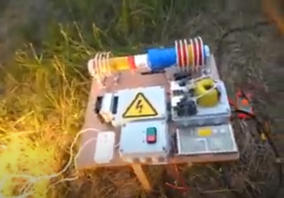
Hello Friends, I will import this thread; from the backup forum to the public category ,it is dedicated to the BTG devices like the ones shown by Ruslan and Akula. The Goal is to gain knowledge about the involved principals, and hopefully to achieve a working, self-feeding machine. Regarding the tier2 category , I want you to know that I was really tented to post for general public, and certainly the thread will be moved in the replications category when the time is right. But I also know that various persons got in serious troubles , and likely a young man lost his live, because this is the kind of devices produced in series would sensibly cut in the profits of the big energy companies.

We will in a first step go in diakoptik manner thru the different parts of the device and make different kinds of experiments and tests to get basic understanding of how this devices are working, and the interaction of the different parts. Also we will collect information from various sources from the original Builders. I would encourage those of you , who are interested in following or participating in this project, to read the thread about longitudinal waves , as this describes one of the  basic physical principals involved in this device.

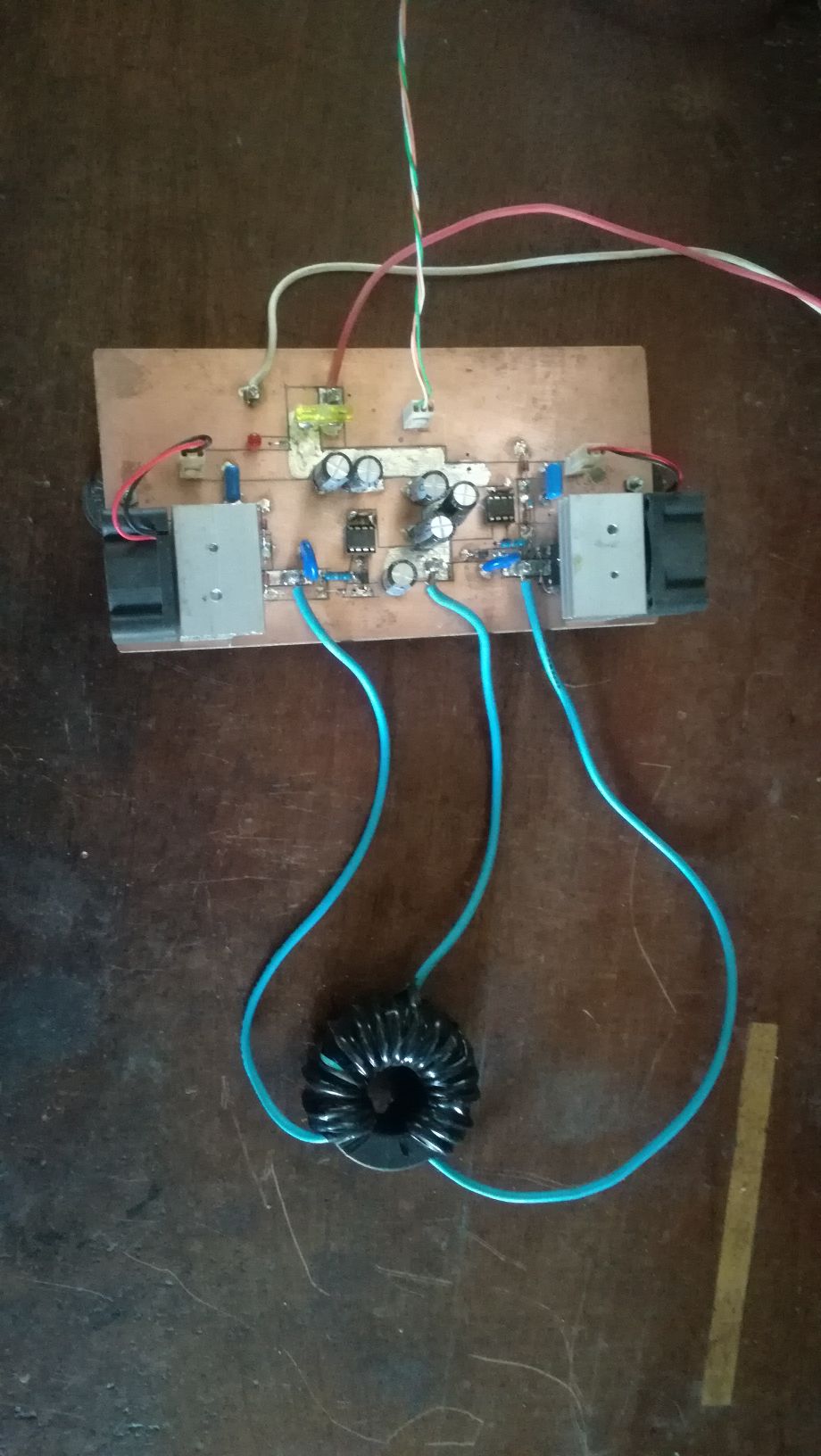
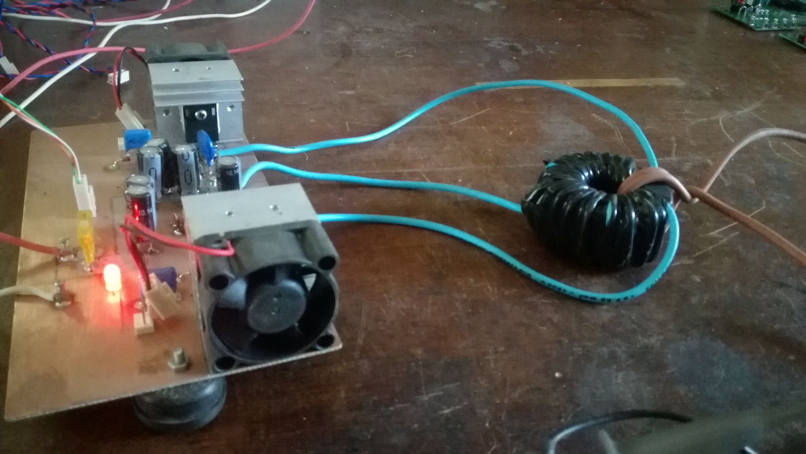
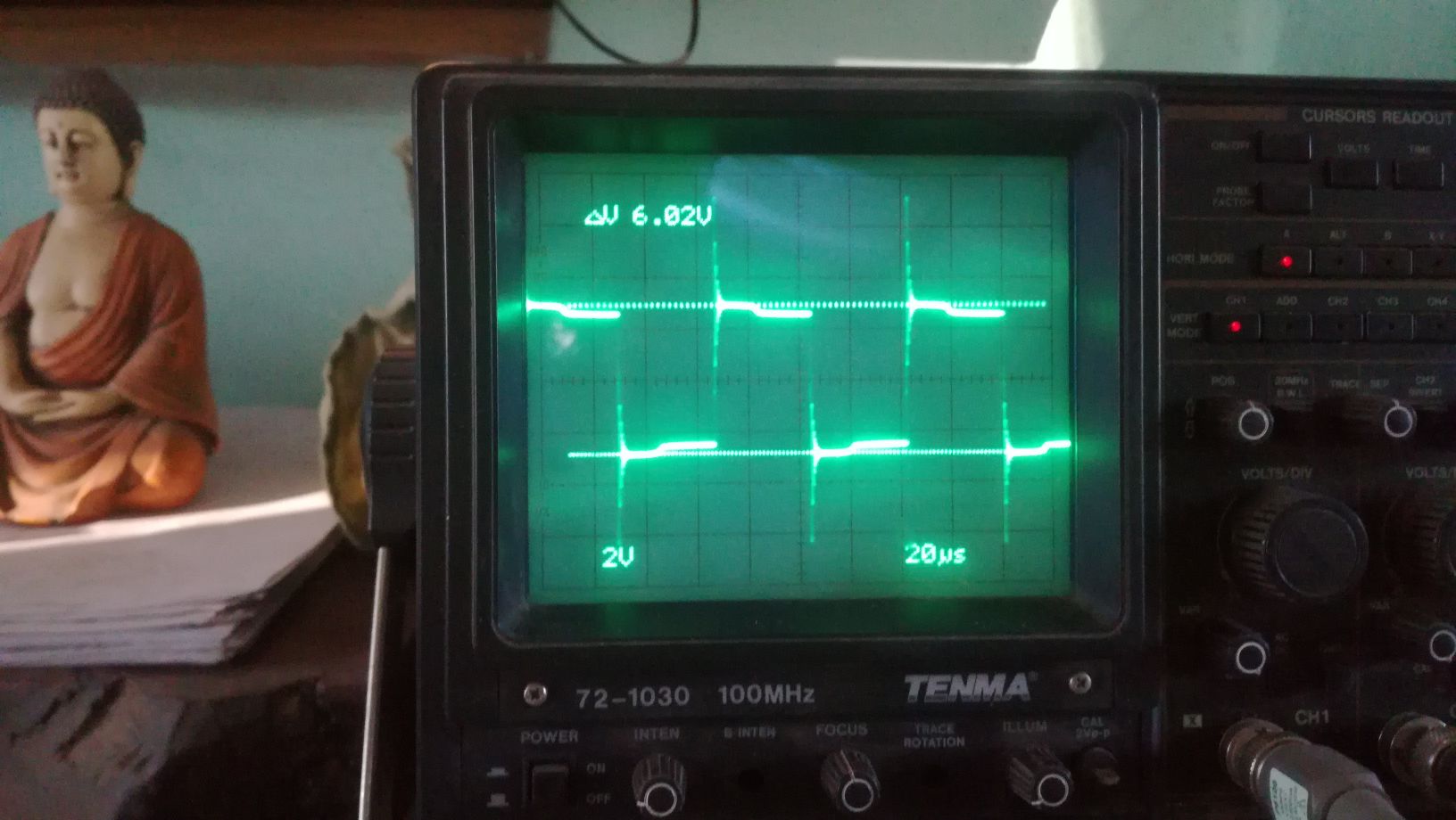
The First Part of the device we will cover is the push-pull converter. It's function is pumping charges, an analogy would be the electron-gun in the CRT, it is the source of charges. There is no magic in this part, it is just common EM technology, there are different topologies which could be used, half or full bridge would be suitable. For low frequency devices like the Kapagen also an of the shelf silicone steel transformer could be used. It is important that the output is AC. In the research we will stick to the push-pull topology for the ease of switching the two low side IGBT's. Here some images from testing this stage:

As I have time ,Ill continue to upload content and updates or corrections.

Vidura

Vidura posted this 20 November 2022

Quoting:Jagau

Hi Vidura

 The experiments with this guy on the resonator seem very much to yours, maybe it can help you, there are 6 other videos like this one on his channel

Jagau

Jagau, these are basic experiments about the antinodes of current, it is not exactly what I wanted to show. The idea is to learn more about the property of the emissions of free oscillations of a resonant coil. There are weird things, it is not like an RF antenna coupling it seems to me.

Vidura

Itsu posted this 21 November 2022


Hi Vidura,

an interesting thread you have here.

This post / video for example:
https://www.beyondunity.org/thread/btg-research/?p=&order=all#comment-0012ef69-8926-4d22-80a0-aee6006bc8c2

shows nicely how much reactive power there is in such a push pull driven series LC combination.
In my Ruslan replication, i measured 50A of reactive current going throug the coil making it hot within minutes.
It would be great to be able to harvest it somehow.

Another interesting topic is here:
https://www.beyondunity.org/thread/btg-research/?p=1&order=all#comment-24dd5df5-06be-4409-9133-aee7006791f1

it concerns the kacher and how we need to get the kacher output (AC) to be transformed to pulsed DC (unipolar) as explained by Ruslan as:  "we need only one half of Tesla, otherwise she will take away what she gives"

Did you ever found an effective way to do that without using rectifiers (which did not work as i understand)?

Itsu

Vidura posted this 22 November 2022

Replying To: Itsu

Hi itsu, it is not difficult at all to remove power from an resonant system, but if there is no recovery of power simultaneously there will be no OU still, the oscillations will die out. Regarding the HF pulses, lately I believe that rectification is not needed, it seems to work like the pressure of sound waves, only the positive wavefront has an effect on nearby objects . Regarding the comment of Ruslan, it doesn't refer to the HF , but to the secondary resonator ( modulation winding , can be separate or combined with the output winding depending on the design). The HF pulses have to be in phase with the second quadrant of the period(potential). They have to be applied during not more than a quarter of the period, because then the current change the sign(direction). Therefore it is parametric excitation, a quarter of period corresponding to twice the frequency of the secondary oscillations. Remember the test for the resonance of the metglass core suggested by Yoelmicro, the excitation is a quarter of period (25%dtc).

Vidura

Itsu posted this 22 November 2022

Vidura,

thanks, so when you say "Regarding the HF pulses, lately I believe that rectification is not needed," do you mean that you have come back from your (2nd part) statement in the linked post where you say:
"There are at least two conditions necesary to get: the modulation of the HV wave has to be in phase with the lower frequency oscillation, and very important, only one polarity of the former 
have to be applied".

I mean your "only one polarity of the former have to be applied" statement.

So the AC coming from the kacher (say 1.2MHz) is OK to use but only when in phase with the second quadrant of the period of the push pull frequency (say 24kHz)?

Thanks,  Itsu 

Vidura posted this 22 November 2022

Replying To: Itsu

Yes this is correct, after making many experiments, I came to the conclusion that rectification is not needed, and maybe even not possible at such high frequencies. It can be done with unipolar pulses also I believe, but from another source, not a resonator. Sorry that I come with an analogue again, but if you like make the following test: put some small pieces, a few mm size of styrofoam in front of a speaker and turn on a loud sound, low frequency is better notable. You will see, the particles are always repelled, despite that the air molecules move in both directions. The pushing force is always stronger than the relaxation of a medium.

Vidura

Itsu posted this 23 November 2022

Vidura,

thanks again, so you agree with that "the AC coming from the kacher (say 1.2MHz) is OK to use but only when in phase with the second quadrant of the period of the push pull frequency (say 24kHz)".

Did you ever tried that?  I did, but i was not able to do it.

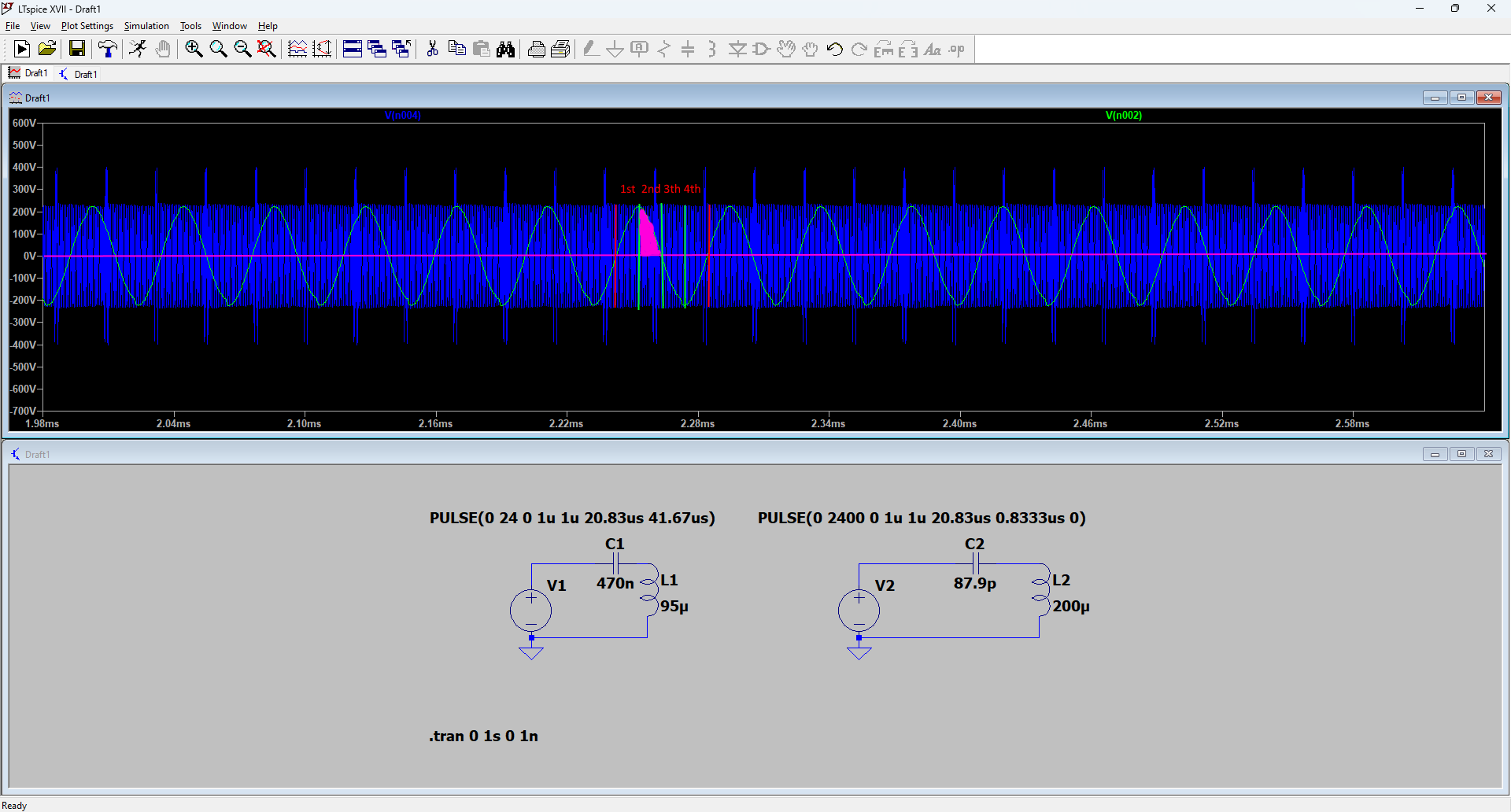
I made a quick LTspice simulation of 2 series LC circuits creating resonance sine waves, one on 24kHz, the other on 1.2MHz to show you my problem.

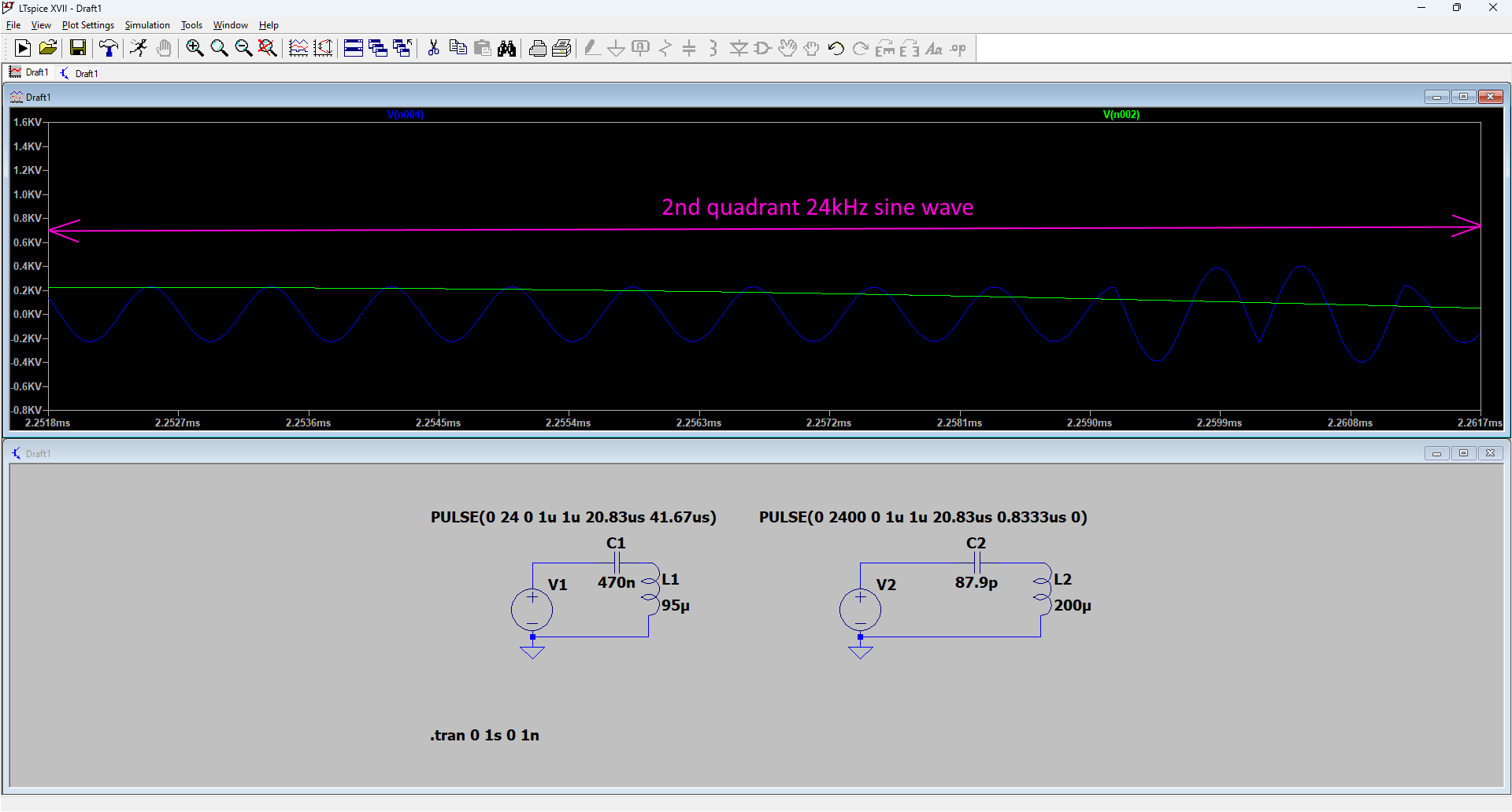
Green is the 24kHz sine wave, blue the 1.2MHz.

In the 1st picture we see the green 24kHz sine wave compared to the blue 1.2MHz sine wave and i have drawn in (pink area) a 2nd quadrant of the green 24kHz signal of 1 period. 
So we need the 1.2MHz (blue) signal to be in phase with this 2nd quadrant of the 24kHz (green) signal, but as can be seen this is not easily doable.


In the 2nd picture i zoomed in on this 2nd quadrant and as can be seen there are many periods of the 1.2MHz blue signal inside this quadrant.

So this was one of my problems then when i replicated the Ruslan setup.

Itsu

Vidura posted this 23 November 2022

This is correct, there can be as many periods of HF as fitting into the second quadrant, but NOT in the other three quadrants, therefore it is necessary to modulate the kacher with 25% dty, at the same 24khz as per your example. This is the way for the parametric excitation. Note that the quarter period pulstrain has to be on the output of the kacher, this has to be adjusted, as the resonator will not stop immediately due to its Q-factor.

Vidura

Itsu posted this 23 November 2022

Vidura,

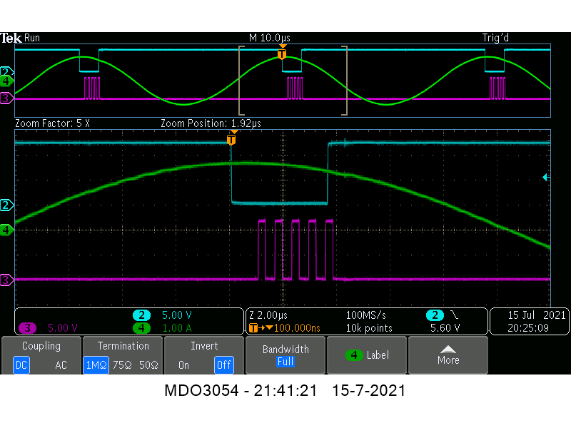
Ok, so i did modulate the kacher (or rather pulsed it) at the 24kHz frequency as can be seen here:
https://www.overunityresearch.com/index.php?topic=3926.msg93638#msg93638

The screenshot shows in green the current through the series LC (24kHz) and in purple the pulse train driving the kacher and we can "move" that pulse train right through the four quadrants of the green current signal.

But despite long tests, no abnormal behaviour was seen, but it could be due to several other problems preventing any abnormality.

Regards Itsu

Vidura posted this 23 November 2022

Have you used the HF source as by Stalker? The scope caption is from that circuit?

Vidura

Itsu posted this 23 November 2022

Quoting:Vidura

Have you used the HF source as by Stalker? The scope caption is from that circuit?

Hi Vidura,


yes that is correct, we attempted to follow Stalker his approach and used his design and thoughts in trying to replicate the Ruslan device.

More details to be found in that long linked thread.


Itsu


Close