
As promised I will import this thread from the backup forum. In first place I want to give credit and express my gratitude to Sergei Deyna, a great Researcher from Russia. He has made a huge number of experiments in diverse areas of physics, and published many papers from which I have used some parts for posting in the forums with his kind permission.
In this thread we will have a look on some basic concepts and principles of AU devices. It is well known from Newtons theory about thermodynamics, that energy cannot be created or destroyed. But it can be transformed in different forms, and it can be collected for our purposes. So if we want to understand, or replicate, or design such a machine, in first place we have to ask two key questions:
1.) Where does the surplus energy come from?
2.)How does this happen, what are the involved physical principles?
Let's take as an example a well-known and accepted AU machine, the heat pump. I think most of you know about this device, which is widely implemented in refrigerators, heating systems, or reversible air-conditioning devices which can operate in both directions. It is well known by engineers, that a modern heat pump can have a COP up to 6( for heating systems with liquid medium temperature exchanger's) . That means for one unit electric power , six units of thermal energy can be obtained. Refrigerators use the very same system, but the obtained heat energy is just wasted without using it.
For the first question it is quite obvious that the extra energy comes from the thermal background energy of the environment (air, water, earth ).
The second question is also not very difficult if someone has some basic information about thermodynamics.
Anyway a detailed analysis will help us for better understanding and give some inspiration for other less known and accepted machines.
We have two main parameters, temperature and pressure.
Under normal circumstances they will have proportional relationship, any increase in pressure will rise the temperature and vice versa.
This relates to a closed system, which does not interchange Energy with the environment, and is also called an adiabatic process. To get a non-adiabatic process, which is of our interest, some specific conditions have to be present. Of course the temperature exchangers on the hot and cold side are required in hardware, as well as a closed circuit filled with a medium. It can be any gas in our case, but for better performance special refrigerant is used, which will experience a change of its state of aggregate from gas to liquid and back, which increases the heat transfer by orders of magnitude. Then we need to create a difference of pressure inside the circuit, usually a compressor will provide the propulsion of the medium, and a release valve will help to divide the circuit into two zones of different pressure. A heat exchanger will be placed in in each zone of pressure.
This setup produces a shift of phase between pressure and temperature, and this is what is making the process non adiabatic, and allows to transfer heat energy from a lower temperature level to a higher one, making possible all the before mentioned practical implementations of this devices.
Now let's make an analysis of another thermodynamic device:
There is another way to create a heat pump without a compressor and refrigerant, in which the working fluid itself (for example, gas) becomes a source of temperature differences and, under certain conditions, is capable of performing mechanical work itself.
Since all thermal phenomena are reversible, then by supplying thermal energy to the machine, mechanical work can be obtained at the output. Such devices are usually called thermoacoustic motors.
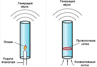
The simplest thermoacoustic machine consists of a resonator in the form of a tube and a regenerator made of a porous material, on the sides of which a temperature difference is created. In the simplest case, the regenerator can be a burner inserted inside the resonator (in the form of a vertically mounted glass tube) or a heated metal porous mesh, as shown in the figure below.
The optimal position of the flame is in the centre of the resonator, and the grid is approximately L / 4 distance from the lower end.
The heat engine or thermoacoustic machine is of special interest for us, as it will help us to understand and draw analogy to various types of electrical self-feeding devices, which uses the principles of resonance.
The theory of the effect under consideration was created by Rayleigh in 1878, in which he discovered the principle that currently underlies all thermoacoustic.
And so, we will compare the principles of operation of the heat pump (generator) and the heat engine:
1) if heat is transferred to the gas at the moment of maximum rarefaction and/or heat is taken away at the moment of maximum compression , then this stimulates the transfer of heat energy.
The thermodynamic phenomenon underlying thermoacoustic is reversible.
The principle of operation of a heat engine :
2) if heat is transferred to the gas at the moment of maximum compression and / or heat is taken away at the moment of maximum rarefaction, then this stimulates gas oscillations.
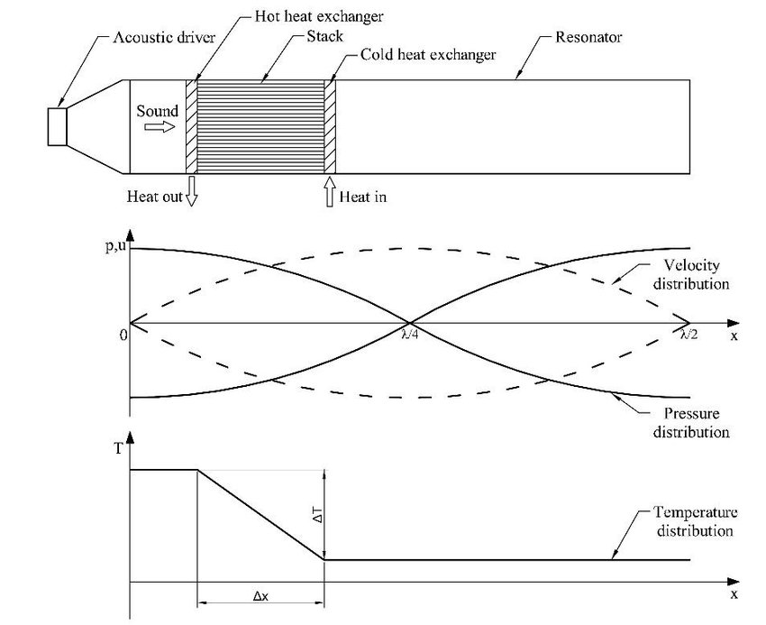
The thermoacoustic device can be based on two modes of resonant oscillations, on standing waves or on traveling waves.
Here standing wave device with the graphs for displacement, pressure and temperature:
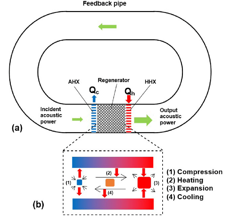
Below we can see a travelling wave device.
And in this video you can see a traveling wave resonator, which is used to produce electric energy from the vibrations of an attached magnet:
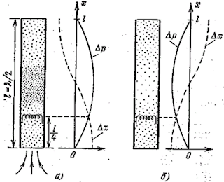
An interesting point is that a standing wave will be established in a half-wave resonator, when pressure and displacement will perform harmonic oscillations. But in addition to pressure and displacement, the working fluid in the resonator also changes the temperature according to a sinusoidal law, especially in the pressure antinodes. Depending on whether the ends of the resonator are open or closed, the pressure antinodes will be located either in the centre of the resonator or at its ends, respectively. The illustration below shows diagrams in which pressure antinodes are visible at the edges and in the centre.
The hydraulic RAM pump is an example for a self-oscillating device, that uses a non-compressible medium to collect energy from a low level source and shift it to a higher one, more suitable for our purposes. There are many different ways to get free energy. Some relative simple to do, others much more complex. Why there are such few replications of the BTG devices from Ruslan, Akula, Kapanazde to name only a few? Are we all that silly that we are not able to replicate? I don't think so, first there are needed skills of various types to build them, and second, and this is the most important cause, we do not completely understand the theories and underlying principles. And this is the main purpose of this thread, to fill the gaps of knowledge.
The reason for analysing the thermodynamic devices is that they will help to draw analogy to the electrical machines, and understand intuitively what's going on.(left brain hemisphere). Thinking about the inconvenience with certain areas of textbook physics, I decided to decline to open disputes against them, as this would only lead to unfruitful discussion with those who are not ready to abandon the obsolete ideas. Instead I will simply trying to show alternative ways of explanations, and try to fit all together in a broader view.
In continuation we will begin to look for the analogies to the electric generators which are based on the principles of resonance for energy collection.
Vidura


