Editor's ZPM replication

  • 4.6K Views
  • Last Post 29 June 2023
editor posted this 07 November 2022

Hello All!

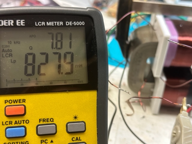
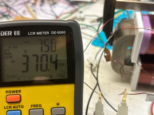
I was in touch with the Fighter and now I decide to show what is going on and to get some new ideas on how to get the signal that we all expect. Below is a quick video showing the simple setup. The coils are 1mm L1 cw 210T (370mH), L2 280T ( 828mH). 


The poles were tested with the phone app named Pole detector, works ok.

I have built some other coils too, with different turn numbers but the output was almost the same.

I have 2 different grounds to play with. I did use the regular power supply but my home appliances were not happy at all, so I decided to isolate everything.

For sure there are differences from Fighter setup, like the core, the position of the coils, the voltage, not sure about the ground.

the video:šŸ˜


bre


Order By: Standard | Newest | Votes
editor posted this 07 November 2022

Hello All!

I was in touch with the Fighter and now I decide to show what is going on and to get some new ideas on how to get the signal that we all expect. Below is a quick video showing the simple setup. The coils are 1mm L1 cw 210T (370mH), L2 280T ( 828mH). 


The poles were tested with the phone app named Pole detector, works ok.

I have built some other coils too, with different turn numbers but the output was almost the same.

I have 2 different grounds to play with. I did use the regular power supply but my home appliances were not happy at all, so I decided to isolate everything.

For sure there are differences from Fighter setup, like the core, the position of the coils, the voltage, not sure about the ground.

the video:šŸ˜


bre


Fighter posted this 07 November 2022

Hi Editor,

First we don't use clickbaits here, so if you don't mind the 10KW part should not be part of the title, let's just call it "Editor's ZPM Replication" ? šŸ™‚ Thanks.

About the turns, the turn ratio of ZPM should be 1:2 ?..

About the ground connection, there should be one as we later found when Chris replicated ZPM even if he didn't made it public.

Regards,

Fighter

"If you want to find the secrets of the universe, think in terms of energy, frequency and vibration."
Nikola Tesla
editor posted this 07 November 2022

Sure, change it no problem.

About the coils, like I wrote I have about 10 of them with different ratios, no big difference.

The ground was connectet to the bulb or the battery, no big difference...

Curently I have no ideas what to do, will try to sleap on it.


bre

Fighter posted this 07 November 2022

For convenience I'll add my latest PM here:


What I find strange is the very low resonance frequency of your device, it's normal to have high consumption at that frequency, my ZPM's consumption is also high when the resonant frequency gets close or below 80 KHz.

What I would do is to double-check that the magnetic fields of the coils are really opposing each other (for example at the top of the core the coils are producing two North magnetic poles oppsing each other) like I do here:

https://www.aboveunity.com/thread/romanian-zpm-zero-point-module/?order=all#comment-12e06a8d-8ff7-427b-9f0e-aa71010204b3

In my ZPMs (I've built two, one is the prototype and the second is a successful replication) as I put more powerful light bulbs on the output the resonance frequency gets lower. So always when I replaced the light bulbs on the output I needed to do another frequency sweep to find the new resonant frequency:

https://www.aboveunity.com/thread/romanian-zpm-zero-point-module/?order=all#comment-5acddfc4-c0cb-4290-b75a-aab300d67f25

In time I learned what is the zone of the resonance frequency associated to specific ligh bulbs or combination of light bulbs so I didn't needed to make frequency sweep anymore.

But even with 2 x 12V/55W light bulbs on output my ZPM's resonance frequency is still 92 KHz, much higher than the resonance frequency you see in your replication:

https://i.imgur.com/stO2VYj.jpg

And I don't know why in your replication the resonance frequency is so low but it explains the missing low input.

Maybe because there is no grounding connection in the circuit ? Or maybe because of the position of the coils, they're closer to each other than on my ZPM and they somehow influence each other ? I don't have the answer for the low frequency right now.

Regards,

Fighter

"If you want to find the secrets of the universe, think in terms of energy, frequency and vibration."
Nikola Tesla
Fighter posted this 07 November 2022

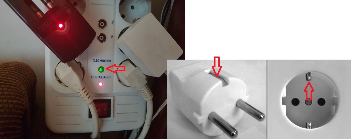
The grounding connection is not something separate like a wire I added.

It's the grounding of the DC source going through the 3rd wire in DC source's power cord and then to the clamps in the power socket to the grounding of the electrical grid:

Fighter

"If you want to find the secrets of the universe, think in terms of energy, frequency and vibration."
Nikola Tesla
editor posted this 07 November 2022

Hi Fighter,


Yes this is common ground, the one that I use in the house. It is connected to the power supply like most of the 

apparatus at home. In this case my fridge is going nuts showing me the predator signs on the display.


That's why I installed 2 different grounds for the lab, independent from the main grid.

Maybe this is the main difference, Because I completely isolate the circuit. It is like when you use 9V batteries,

but I'm not sure if you got the effect in  this scenario, there were no scope shots...


bre


Itsu posted this 07 November 2022

Hi Editor,

looking good and at first glance it looks like you have similar results / signals as i have (no effect / resonance).

What is it we are looking at on the scope, i see a csr (what value?) so i guess its current, but taken from where (input?).

Regards Itsu


editor posted this 07 November 2022

Hi Itsu,

yes I fully agree with you, we have very similar results, unfortunately.

On the scope we are looking at voltage on the bulb. I try earth ground, everywhere no resonance.

Maybe Fighter can do another test with the battery on the input so we can eliminate the PS/battery mystery.

br,e.


Fighter posted this 07 November 2022

Sorry, unfortunately I have no time for experiments right now and I have no 25V battery and charging equipment for it.

When I tried with 3 x 9V batteries they were not capable of maintaining voltage so ZPM was not able to stay on the initial resonance frequency. So as the input voltage drops ZPM will get out of the optimal/resonance frequency so it will start consuming more so the input voltage will drop more and so on. The test was simply not conclusive:


The voltage needs to stay constant so the resonance frequency stay constant. That's what stabilized voltage supplies are for, batteries can't do that especially when consumption is pulsed as ZPM does.

ZPM is functioning as I presented it (in tens of tests and with details) in the configuration I presented it: with DC source grounded to the electric grid's grounding.

I tried to figure out a few possible reasons for the issues you're experiencing when using batteries but if you want to go to a different way than the way I described and shown for sure there may be unforseen problems. And I simply can't identify the causes just by simulating your different circuits in my mind.

My prototype is working that way and also the second ZPM (replica). Also as I shown to you it was replicated in another place, with different equipments but still using DC source and grounding.

Regards,

Fighter

"If you want to find the secrets of the universe, think in terms of energy, frequency and vibration."
Nikola Tesla
editor posted this 07 November 2022

Ok, I understand. 

Will try to do two more test:

  • raise the voltage to 25V or more with DC-DC converter
  •  connect everything to one power source ( accu) and add external ground to minus terminal

have a nice day or night, e

editor posted this 08 November 2022

Hello all!

The two tests mentioned above was done, unfortunately with no positive results or

magnetic resonance. Currently it looks like the challenge is related to the power supply.

I will not continue with the power supply connected to the grid. 

Maybe some time is needed to think what to do next if any, maybe PS connected to the inverter and battery... well see.


br, e

Close