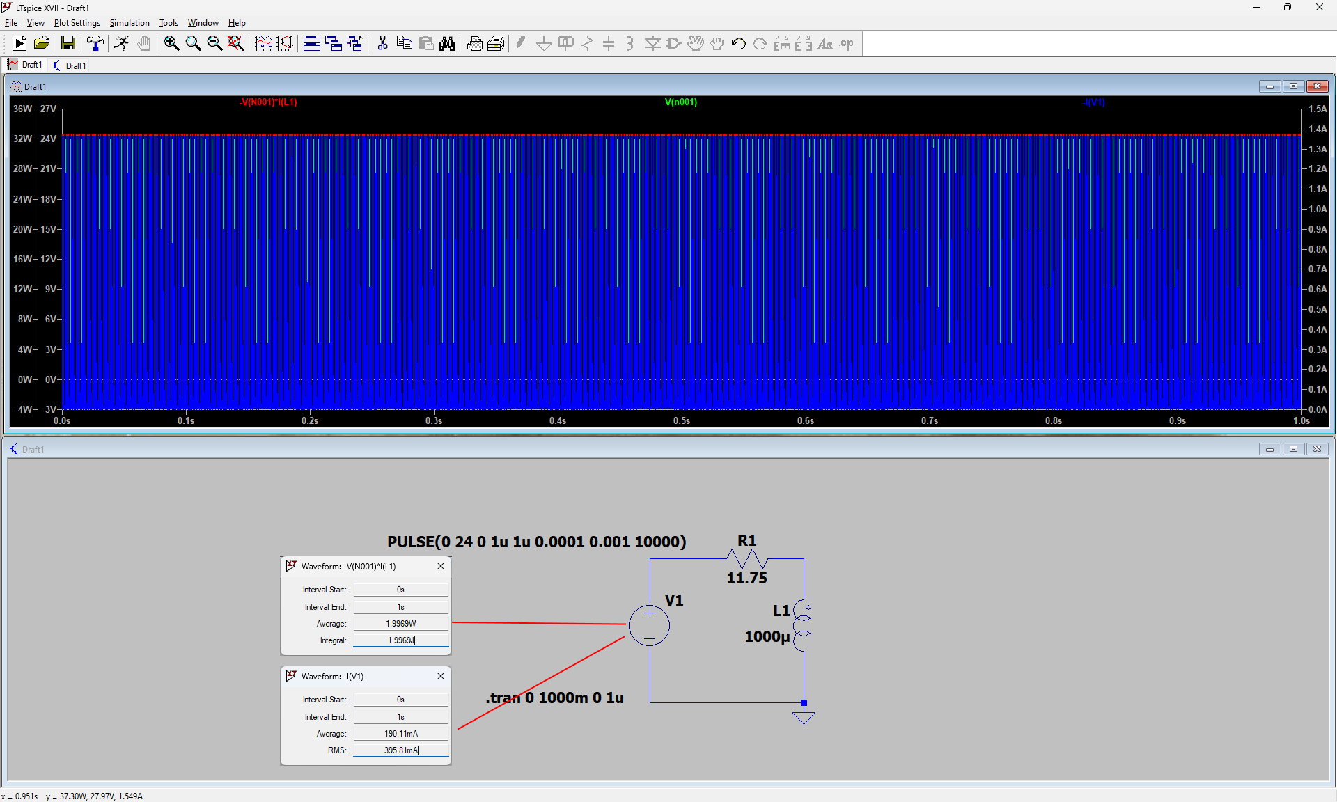
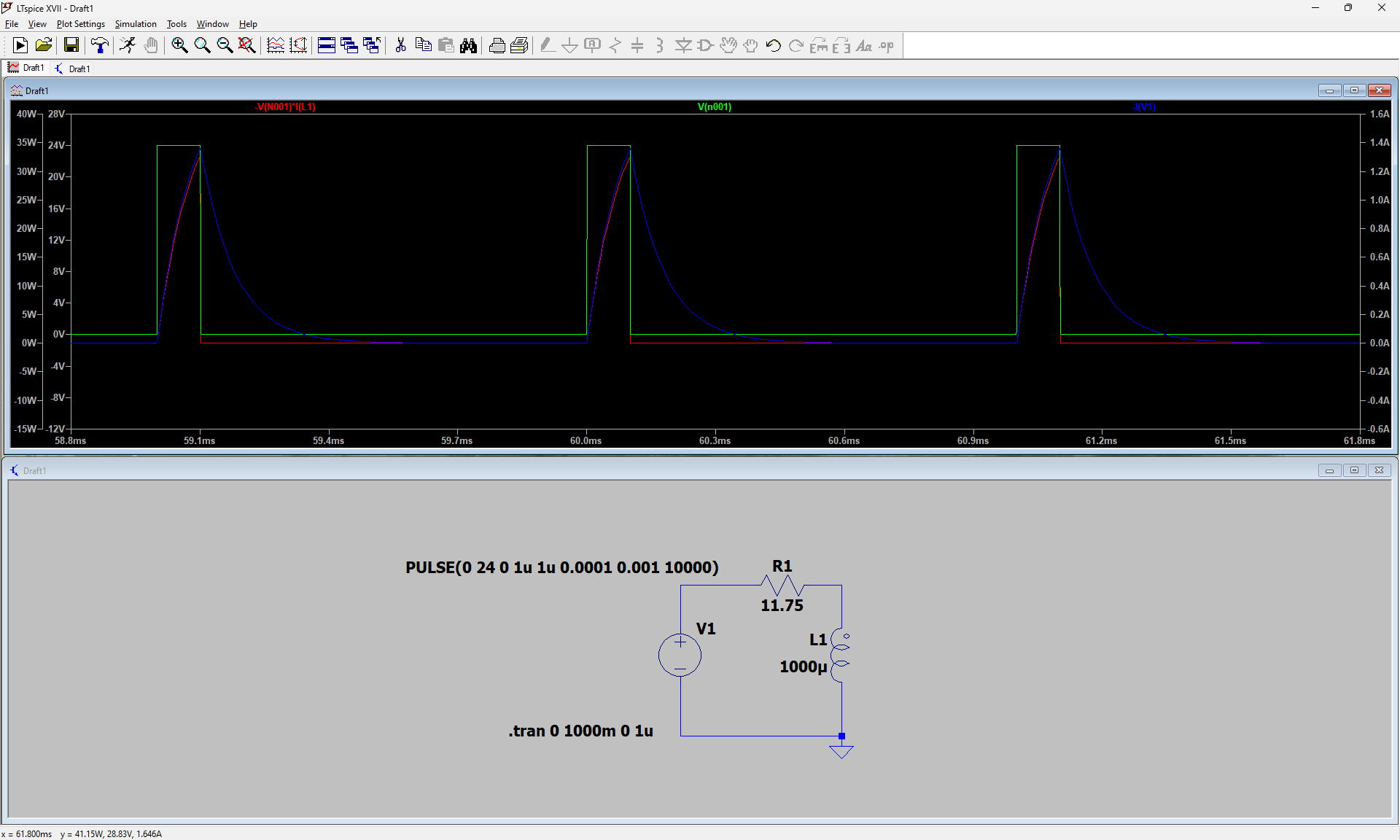
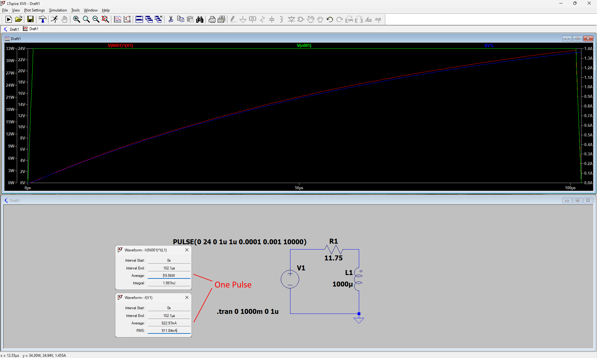
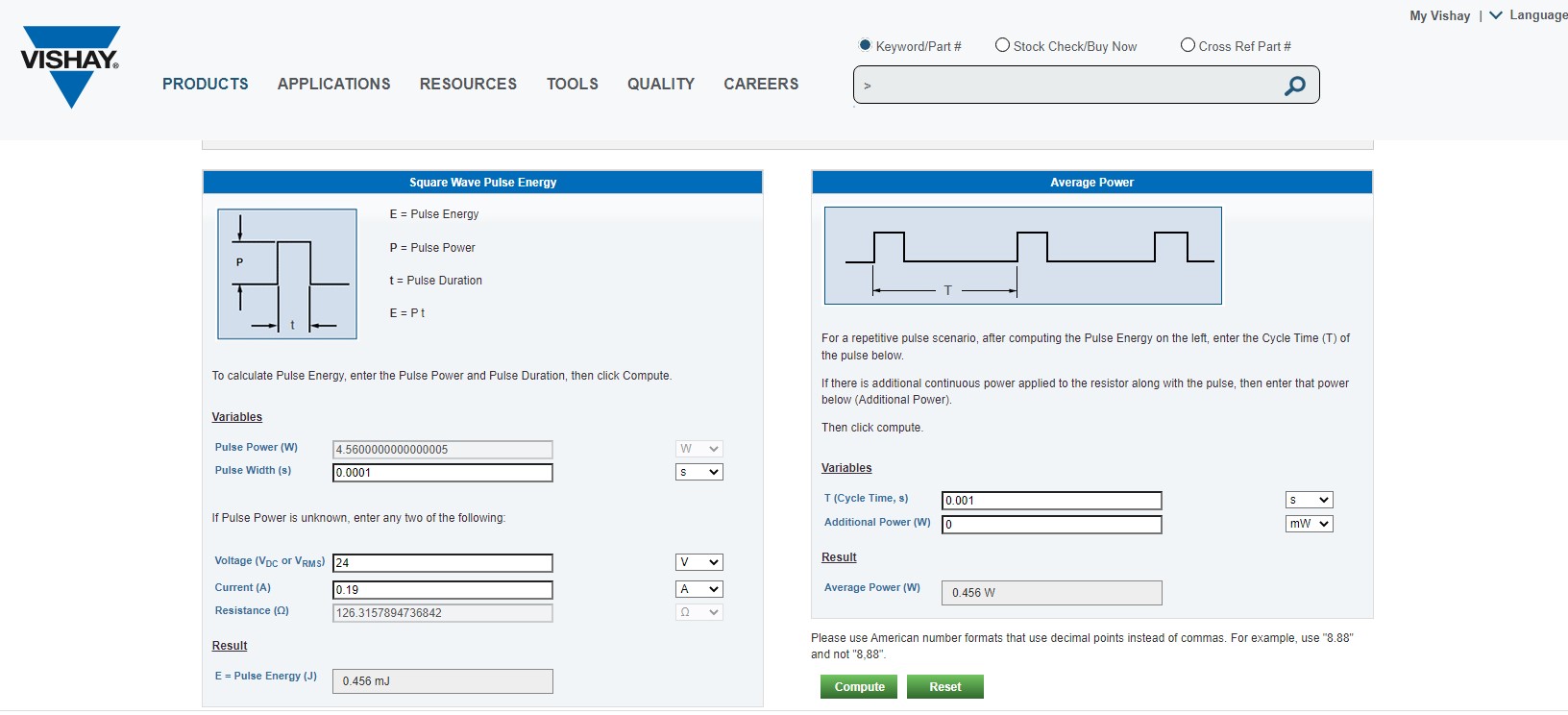
Discussion on how to calculate the energy of a square wave or PWM waveform
Not to be confused with an AC square wave which changes polarity.
We are very often confronted with having to take measures that are reliable, this open discussion will surely be able to enlighten us in order to be sure to take the right measures.
First of all I would like to say that to take measurements on a PWM, the oscilloscope is the ideal instrument for this purpose, but it must be well programmed and certain functions are not accessible for all models.
For those who don't know, a DDM will never get the correct measurement from PWM, either for voltage or current. Even if you used a True RMS meter, your reading will not be good, same for a standard DDM.
Some DDMs have the ability to do this but they are rare, this one if found it does not remove the DC offset but most DDM have false measurement. Even my 2 expensive fluke DDMs should not be used for PWM reading. With square waves AC it is correct the measurement will be good.
There are nowadays ways to check with a good scientific calculator, so you can be sure of your measurements, everything is calculated manually too.
Let's start if you want by calculating the energy of a PWM input average power
Jagau