Fighter's ZPM (Zero Point Module) failed replication by Itsu

  • 8.1K Views
  • Last Post 18 December 2022
Itsu posted this 07 November 2022

Hello all,

i opened this thread to discuss my replication of Fighter's ZPE (Zero Point Module).

I already opened a similar thread on OUR.com (https://www.overunityresearch.com/index.php?topic=4374.msg101654#msg101654 ), but will transfer some data from there to here.

Initially i understood that the below diagram was correct and complete, but it turns out its not.
There is a ground connection somewhere, but i am not sure where it is exactly, hopefully someone can tell me.
The MOSFET is shown wrong as the Drain and Source should be swapped, which was corrected later in Fighter his thread so therefor the mentioning in red.

I have build up a similar circuit and the data is shown here: 
(Be aware that the induction measurement was done at 10kHz, but due to the influence of the metglas core it can be (and is) completly different on other frequencies, see my thread on OUR.com for a VNA scan of the coil/core)


I am using a 12V battery for now as my PS (minus NOT grounded) was acting weird due to all the pulses coming back from the ZPE device.
Up till now no special effects or resonance in a 0 to 5MHz range are seen with this setup, but as said the grounding may be the problem here.

Itsu

Itsu posted this 28 November 2022

Vidura,

thanks foir the advice, but i am not able to get the core to saturate, even when loaded.

So i followed this video: https://www.youtube.com/watch?v=T81oiXqd-WM  which basically shows how to measure the saturation current of a ferrite transformer.

Following this setup and using a small 6mH ferrite transformer as in the video i was quickly able to show this saturation point, using 13V input at 6% duty cycle see screenshot:

But when using the opposing coils on the metglas core i am not able to saturate the core even when several amps flow through it.
I tried with the single coils too, but same results, no saturation, see screenshot of opposing coils, using 13V and 50% duty cycle:

Pushing the input voltage to 40V and duty cycle to 90% causing an average 7A flowing through the coils also did not cause any sign of core saturation.
So it seems to me that saturating this metglas core is no easy task and i doubt if in Fighter his setup there is saturation of the core going on.

Please correct me if i am wrong or made any mistake somewhere.

Itsu

YoElMiCrO posted this 28 November 2022

Hello everyone.

@ Itsu.

Yes, I realized later that you only showed the gate signal, hehehe.
But it is easy to see that the mosfet is in saturation mode...
First you comment that it does not heat, that's because it's working 
in the saturation zone and not in the linear zone.
Second, as you go up the DTC the current rises, because it is
in the saturation zone, that's what you actually see on your oscillograph.
Those are the symptoms that the mosfet works as it should.
On the other hand, amorphous/nanocrystalline materials possess
a ratio between Br/Bs almost equal to 1, this means that it is very
easy to see the saturation of them and they are the best materials
for applications in Fordward, due to its narrow region of hysteresis and
Br/Bs ratio approximately equal to 1.
The core saturate for two reasons, one is by voltage and the
another by current.

For some reason I can't understand, you're not able to suture it.
When I proposed the test, I meant...
With the same inductors you have, only power in the center
and mosfet in any of them.
You should be able to suture it.
In the case of Fighter's ZPM, yes or yes it saturates, there's no doubt about that.
The current shape is like the image of the previous thread.
Fighter also shows it with its oscilloscope.

I hope it helps you.

YoElMiCrO.

  • Liked by
  • Inception
  • Vidura
Itsu posted this 28 November 2022

YoElMiCrO,


But it is easy to see that the mosfet is in saturation mode...
First you comment that it does not heat, that's because it's working 
in the saturation zone and not in the linear zone.

i always try to operate the MOSFET (when used as a switch as in this circuit) in its active (saturated) region by switching the gate as quick as possible above its Vgs threshold level.
When operating such a MOSFET in its linear region you are asking for heating up the MOSFET and is to be avoided.


Second, as you go up the DTC the current rises, because it is
in the saturation zone, that's what you actually see on your oscillograph.
Those are the symptoms that the mosfet works as it should.

Yes, as i am looking for the CORE's saturation point i need to increase the DTC (Duty Cycle) to increase the current in search for the CORE's saturation point.

On the other hand, amorphous/nanocrystalline materials possess
a ratio between Br/Bs almost equal to 1, this means that it is very
easy to see the saturation of them and they are the best materials
for applications in Fordward, due to its narrow region of hysteresis and
Br/Bs ratio approximately equal to 1.
The core saturate for two reasons, one is by voltage and the
another by current.

 
Ok, so why do i NOT see the current sharply increase to show the CORE is starting to saturate?
I vary the current from almost 0mA to 7A, but this sharp current rise indicating saturation of the CORE does not happen.

For some reason I can't understand, you're not able to suture it.

Not sure what you mean by suture,   saturate?        If so, then i also do not understand that.

When I proposed the test, I meant...
With the same inductors you have, only power in the center
and mosfet in any of them.
You should be able to suture it.

Ok,  so only use one of the both coils, not both in opposing mode.
Well i did that trying to find the saturation point as mentioned in my above post, but also with only 1 coil i cannot find the current to sharply increase thus get it into saturation.


In the case of Fighter's ZPM, yes or yes it saturates, there's no doubt about that.
The current shape is like the image of the previous thread.
Fighter also shows it with its oscilloscope.


So there is a scope screenshot from Fighter showing this sharply rise of the current?
I will look for that, i guess its when he uses a csr (shunt).


By the way, in the specs of the AMCC 200 core i read that it takes 1.56T to saturate, which seems to me a very high value.


Thanks,  regards Itsu 

Itsu posted this 29 November 2022

I used my both coils (300 turns) in series aiding and measured it to be 705mH @ 10kHz.
I pulsed these 300 turns with 8A average (41V input, 90% duty cycle, 1kHz), but still no saturation point seen in the current trace.

Using this webpage: https://www.magmamagnets.com/magnets-technical-information/conversion-tables/   i transferred the Ampere-turns via Gauss to Tesla:

300 turns @ 8A = 2400 Ampere-turns

2400 Ampere-turns = 3016.8 Gauss   (x 1.257)

3016.8 Gauss = 0.3T   (x 0.0001)


If this is thru (the conversions), then this 0.3T should NOT be enough to saturate the AMCC 200 core (1.56T needed) so it makes sense i do not see the saturation point in the current trace.

I cannot find any screenshots from Fighter showing his current making this saturation jump, so any help would be appreciated,   Thanks.


I have some 0.8mm magnetwire on order, so when it arrives i will rewind my coils the way Fighter has at the 150 / 300 turns relation and start new testing.


Regards Itsu

  • Liked by
  • Inception
  • Fighter
Fighter posted this 03 December 2022

Hi Itsu,

Sorry for the late reply but I was very busy with my job work.

So there is a scope screenshot from Fighter showing this sharply rise of the current?
I will look for that, i guess its when he uses a csr (shunt).

No, all the screenshots containing scope images when checking what's going on in ZPM's coils are showing voltages only.

The reason I didn't used a shunt resistor on ZPM's coils is simple, I just want to let ZPM's coils keep their natural resonance frequency. Don Smith says any resistor or capacitor connected to a coil will always move its resonance frequency lower, moving it away from its natural resonance frequency which is fixed and it's related to the wire length of the coil (and of course the core used but that's not a variable).

It's not necessary to check the current in the ZPM coils to see what's going on there (like the variation of magnetic field, saturation, etc.), the voltage can get a pretty good image of that.

Let me explain the rules I use:

Inductor Voltage and Current Relationship

  • The instantaneous voltage drop across an inductor is directly proportional to the rate of change of the current passing through the inductor;
  • The inductor's self-induced voltage has a polarity that opposes the change in current (Lenz's Law);
  • The mathematical relationship is v = L (di/dt).

You can find more details here:

https://www.allaboutcircuits.com/textbook/direct-current/chpt-15/inductors-and-calculus/

So a basic rule I use is like this: when the current and magnetic field(s) go up the voltage goes down, like in a mirror.

Let's use as an example one post in the ZPM thread here:

https://www.aboveunity.com/thread/romanian-zpm-zero-point-module/?order=all#comment-ec688fa0-4e9e-432f-9d84-aa98018240f9

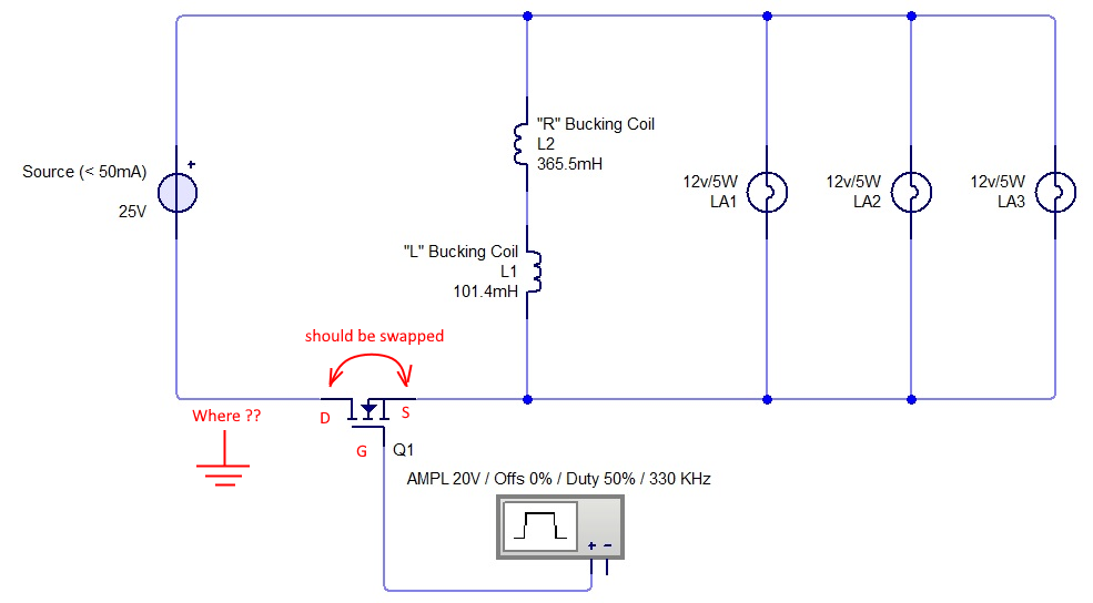
The scope's probes are connected this way:

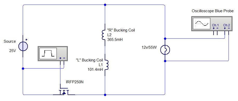
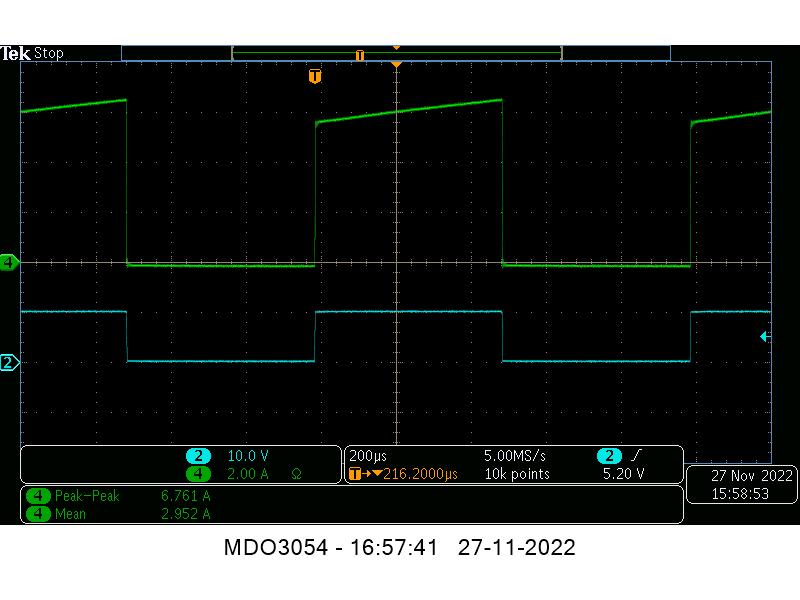
And this is a screenshot of the scope when using a 12V/55W light bulb on output (just ignore the "blue probe" text from the above image, in the next image I'm using the yellow probe):

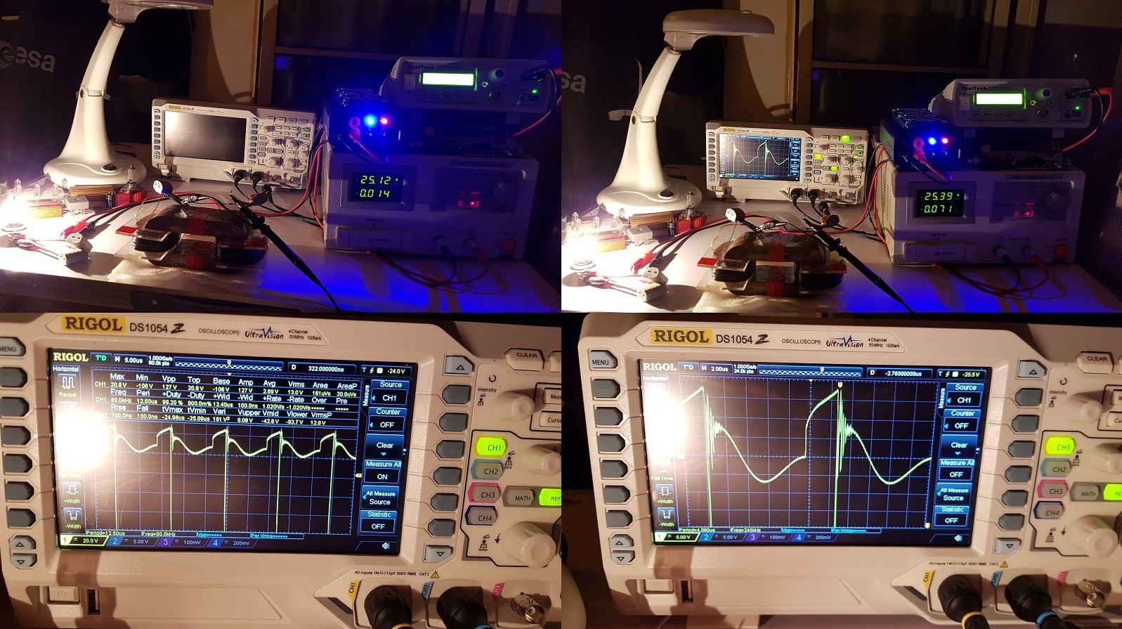
You can see the core saturation process Yoel is talking about, it's very short (and may not be a full core saturation, I don't know that): when voltage is going down from Vmax=20.8V to Vmin=-108V. In that very short period the current in the coils is building up fast generating negative voltage. Then the current therefore the magnetic fields are dropping fast generating positive voltage reaching the region where the coils start ringing or "dancing" with each other. That region where voltage go up and down fast means the current therefore magnetic fields are fluctuating up and down fast and that is happening without any help from the input. Magnetic fields fluctuating fast without the help of the input means there we gain extra-energy.

So the core saturation is present for a very short time, I don't know if it's 100% saturation but its very significant, look how fast and how far the voltage becomes negative. It may be a full core saturation just for a very-very short period in that pulse, why not ? There is no way to verify that right now.

That ringing is present and very visible when there are heavy loads on ZPM's output, like one or two 12V/55W light bulbs.

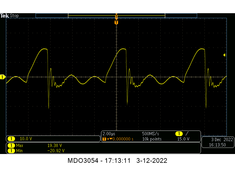
Let's take a look now at the situation when there is a small load on ZPM's ouput, like one 12V/5W light bulb:

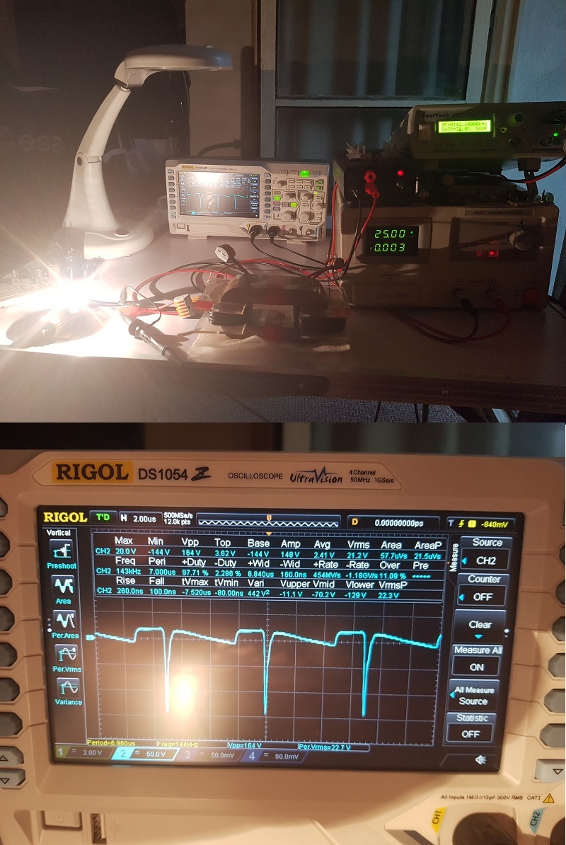
You'll notice the saturation period is much faster and steep, the Vmin is going now to -144V. Then the current therefore the magnetic fields are collapsing and when they try to stabilize themselves they're doing it more precisely, without that ringing period while going slowly down to 0 until the new pulse is coming from input starting to charge up de coils again.

When looking at these images keep in mind that the duty-cycle is only 25-30% so the input is acting only when the coils are charged, the other actions like magnetic fields collapsing, the "dancing" of the coils until reaching 0 voltage - all these are free actions occuring without the help of the input and all these actions/variations are generating energy.

This is how I see what's going on in ZPM's coils without measuring current using a shunt resistor but just letting the coils run free at their natural resonant frequency and just watching the voltage.

And just one guess: in an ZPM with a bigger core capable to power bigger loads (like 3-4 12V/55W light bulbs) that ringing period or the "dancing" of the coils will be much longer and much higher; and remember, those actions are not using the input at all and all those variations of the magnetic fields are producing extra-energy.

I hope this helps and again, this is just my understanding of what's going on inside MEG and about the saturation process Yoel is talking about. Any correction from other members is welcome.

Regards,

Fighter

"If you want to find the secrets of the universe, think in terms of energy, frequency and vibration."
Nikola Tesla
Itsu posted this 04 December 2022

Fighter,

thanks for your information and your theory.

I have some doubt about that theory as i don't think what you see on that screenshot has anything to do with saturation of the core.

But firstly, did you ever try to insert a 1 or 0.1 Ohm shunt resistor to see if the "effect" was gone?

I mean if it is still there with such a shunt, you can use it as a current sensing resistor to do some current measurements.


Anyway, here my 2 cents on what i see happening with the voltage across the bulb, it looks to me normal switching behavior when a coil is being switched on and off

It seems you are in resonance looking at the sine wave like signal of the yellow voltage, then we see the switch activate and the current and voltage increases (20V) meanwhile building up the magnetic field.

At the next moment, the MOSFET switches off, causing the current to stop, the magnetic field to collapse and BEMF created (negative 108V) followed by some ringing caused by the capacitance (coil, wires) and inductance (coil, bulb filament) and then the cycle repeats.

So, i do not see this negative 108V to be caused by the saturation of the core, i think it’s just the BEMF caused by the collapse of the magnetic field after the switch opens.


Here i measure also the voltage across my bulbs (2x 21W plus 3x 5W = 57W) and it shows a similar signal as you.

My BEMF spike is less which could be due to different load (bulbs) and/or different coils (less turns).

Itsu

Fighter posted this 04 December 2022

Well, I guess we see things differently.

I would totally agree with you if what I shown on my scope would be current, but it's not, it's voltage.

"The inductor's self-induced voltage has a polarity that opposes the change in current".

So when the current / magnetic field is raising, a voltage with opposing polarity (therefore decreasing) is shown.

In my opinion if you want to see what's going on with the current / magnetic field on my scope you just need to place a mirror on top of a scope image and look at the image shown by that mirror.

That would give a approximative idea about what's going on in the coils without using a shunt resistor which will modify the resonance frequency of the coils.

But that's just my opinion, of course, let's agree to disagree. šŸ™‚

And no, I never used a shunt resistor connected to the coils for the reason I explained. And I can't test the scenario because there is no time for experiements and the wires of the ZPM circuit are somewhere in some boxes mixed with other similar wires, I would need time to find them and identify them. There is no time to resume experiments for now, sorry.

Regards,

Fighter

"If you want to find the secrets of the universe, think in terms of energy, frequency and vibration."
Nikola Tesla
  • Liked by
  • Atti
  • Inception
Atti posted this 04 December 2022

Itsu.


Where do you want to put the csr (shunt) resistor? On the input side or the output side?

Atti

Vidura posted this 04 December 2022

On the load it would be interesting, to observe the direction and phase of the current.

Vidura

  • Liked by
  • Fighter
  • Inception
Itsu posted this 04 December 2022

Fighter,

thanks for info, yes, lets agree to disagree,  perhaps someone can shed some light about it.
I will try to make some more measurements.


Atti,

Where to put the csr would be depending on what to measure.

For measuring the saturation current, it would be at the minus lead of the PS like i show in my first post here:
https://www.beyondunity.org/thread/fighter-s-zpm-zero-point-module-replication-by-itsu/?p=1&order=all#comment-45114712-0ecd-4c3b-a359-af4600610d45

It would also be the most convenient place when using a grounded scope.

But as Vidura mentioned it could be interesting to measure the current through the load (bulbs), but that requires the scope to be isolated, the DUT (Device under test) to be isolated, using the differential probing technic (2 probes using minus Math) or use a current probe.


Vidura,

Using my current probe i can make a current measurement at almost any place in the circuit, so i will see what i can do using the current probe in the load line.


Itsu

Close