Jagau's successful ZPM replication

  • 3.8K Views
  • Last Post 30 June 2023
  • Topic Is Solved
Jagau posted this 09 December 2022

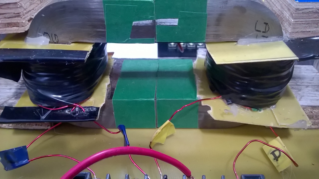
My replication of Figther's ZPM. As my two coils were already mounted on an AMCC320 I was able to replicate quickly.
In the first image the 2 coils mounted on the AMCC320


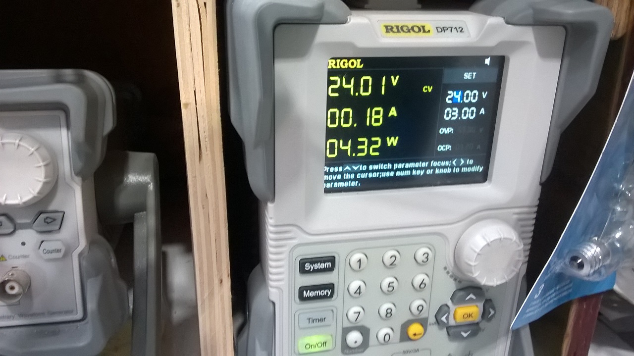
In the second image when the power supply is turned on at 24 volts DC he sees an input power of 4.32 watts on 24 volts and 180 ma when my TL494 oscillator is supplied to both coils through an IGBT pulsed at 38.2% on the high side. Channel1 is IGBT pulse 


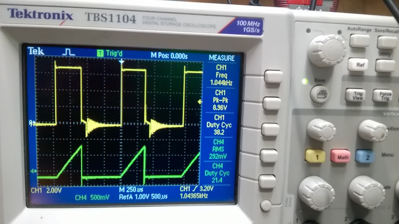
Image of the oscilloscope with the current probe on the PS

You can notice that the oscilloscope show on a my TEK current probe (green) 292mv =292 ma  (rectangular form) and 38.2% DTC

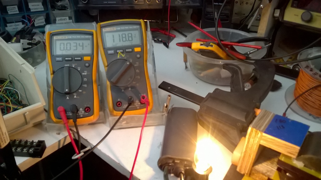
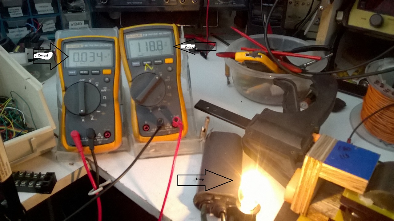
Last image the 118 volt 4 Watts lamp lit with 34 ma x118.8v = therefore 4.0392 watts of power produce at the output on a large capacitor and 4 diodes in parallel in order to produce an almost pure DC which can be read by the 2 DDMs

Calculation of input power in DCM mode with reactive component.

As indicated by the power supply we have an instantaneous pulse power of 4.32 watts, this is the instantaneous power not the average power over time.

V and I is what PS provided a DM as wrong lecture for input due to high frequency so to calc PIn we take well known formula for inductor.

Irms on scope is 0.292 Amp, DC voltage is 24volts

Pin= I*V*sqrt(Duty_Cycle)/sqrt(3)


Pin= 0.292 Amp x 24 Vdc x sqrt 0.382 / sqrt 3 = 2.533 watts

So for  Pout of 4.032 watts  i need only 2.533 watts at input, Still a pretty good COP
Jagau

Order By: Standard | Newest | Votes
Jagau posted this 09 December 2022

My replication of Figther's ZPM. As my two coils were already mounted on an AMCC320 I was able to replicate quickly.
In the first image the 2 coils mounted on the AMCC320


In the second image when the power supply is turned on at 24 volts DC he sees an input power of 4.32 watts on 24 volts and 180 ma when my TL494 oscillator is supplied to both coils through an IGBT pulsed at 38.2% on the high side. Channel1 is IGBT pulse 


Image of the oscilloscope with the current probe on the PS

You can notice that the oscilloscope show on a my TEK current probe (green) 292mv =292 ma  (rectangular form) and 38.2% DTC

Last image the 118 volt 4 Watts lamp lit with 34 ma x118.8v = therefore 4.0392 watts of power produce at the output on a large capacitor and 4 diodes in parallel in order to produce an almost pure DC which can be read by the 2 DDMs

Calculation of input power in DCM mode with reactive component.

As indicated by the power supply we have an instantaneous pulse power of 4.32 watts, this is the instantaneous power not the average power over time.

V and I is what PS provided a DM as wrong lecture for input due to high frequency so to calc PIn we take well known formula for inductor.

Irms on scope is 0.292 Amp, DC voltage is 24volts

Pin= I*V*sqrt(Duty_Cycle)/sqrt(3)


Pin= 0.292 Amp x 24 Vdc x sqrt 0.382 / sqrt 3 = 2.533 watts

So for  Pout of 4.032 watts  i need only 2.533 watts at input, Still a pretty good COP
Jagau
Jagau posted this 12 December 2022

 Hi BMW

Ok It was faster than I thought, for your answer I did a Cursor Measurements, the time of a complete period is 25 us or more precisely as displayed on the 39.68 Khz oscilloscope

jagau

Jagau posted this 09 December 2022

Again the only lamp lit has a DDM of 34ma and a voltage of 118 volts

to know the COP Pout / Pin
it is so complicated? no just a little understanding

For those who doubt it's your right, I don't want to convince anyone here but it's already in the past for me, these are old experiences. In order to have more precision in my data I used a dedicated current probe for oscilloscope, accurate up to 50Mhz, which is very different from the shunt resistor.

Jagau

Atti posted this 09 December 2022

That's what it's about. This is exactly why I need to buy a bigger Amcc. The strength of the effect is clearly visible. As others have suggested: LET'S EXPLORE THE EFFECTS. It can be seen that it will have results.

  • There must be some reason for the operation. So the reasons must be collected.
    - There must be a reason for the unsuccessful operation. This is the opposite of the previous statement.

Atti.

Jagau posted this 11 December 2022

ok i see what you want
when i go back to my lab ok

Jagau

bigmotherwhale posted this 12 December 2022

Thanks Jagau, if this is not an LC phenomenon, then you have a propagation speed of around 8000 m/s in your core with a 32cm magnetic path, please correct me if im wrong maths isnt my strong point.  

could you try altering the capacity of one of the coils with a capacitor and measuring again or try pumping the core at this freqency?  

bigmotherwhale posted this 12 December 2022

Lm mm = 328 so not too far off from 32cm 

Its debatable if thats the right way to calculte as you have a change in aspect ratio at the opposing coil so the wave would be at least partially reflected if it was conducting at that point. 

Jagau posted this 13 December 2022

Curiosity is a very important tool in research like we do. No problem with that BMW

In another order of idea, with regard to the ZPM the type of load is very very important.

Having tested different configurations, it should be non-linear, as an incandescent lamp can and the combination of nominal operating voltage and power is proportional to what you will get at the output.

Jagau

Fighter posted this 22 December 2022

Hello friends,

Jagau asked me to lock his threads until he returns.

He needs to take care of some personal things, he will give more details when he returns.

Regards,

Fighter

"If you want to find the secrets of the universe, think in terms of energy, frequency and vibration."
Nikola Tesla
Atti posted this 31 March 2023

Hi Jagau.


You can read and read the details here. Watch Cap4 video.   https://www.beyondunity.org/thread/atti-s-successful-zpm-replication/?p=3
 The power source is not a laboratory power supply but a battery.12V+18V .  
The current and voltage values taken from the battery are also shown.  The phase relationships are also shown.  


Atti.

AlteredUnity posted this 31 March 2023

Hey Jagau, I have plenty of components at my disposal and seeing the promising results(even in my experiment though the coils are wound opposite.) I am interested in your diode(s) and output capacitor configuration. I haven't took the time too hook up my siglent for readings, and apply your formula, but think it could really simplify my measurments. Ps. Last time I tried tuning a 120v load it tripped my plugs gfi, and can't remember but may have tripped circuit breaker too.

Close