Behavior and analysis of the inductor

  • 1.3K Views
  • Last Post 14 February 2023
Jagau posted this 07 January 2023

The behavior of an inductor in an electronic circuit has very interesting phenomena to observe. The purpose of this thread is to study some of them using a simple circuit.

Jagau

Shelfordella posted this 29 January 2023

How -∂A/∂t vanishes from the E-field equation E=-∇φ -∂A/∂t by the Lorenz gauge, like Bearden said happens (too advanced for me, but interesting):


More info:

https://en.wikipedia.org/wiki/Retarded_potential

https://en.wikipedia.org/wiki/D%27Alembert_operator

https://en.wikipedia.org/wiki/Lorenz_gauge_condition


"A little theory and calculation would have saved Edison 90 per cent of the labor." Nikola Tesla

Jagau posted this 03 February 2023

Hiall

In taking measurements when you have inductors with a behavior with a lot of RF around, I would like to share with you a part of the unfinished work of Dr R. Stiffler who gives excellent advice in taking measurements  with an inductor while avoiding the potential for error readings caused by the powerful electric fields with a lot of RF.
I count on one day humbly continuing his work.

Here is the schematic of a way of connecting its DDM with good reading measurements.


AV plug is if you have one in your circuit, no need of it you do not have one in your circuit.

The ferrite beads are there to eliminate RF interference, we can adjust them to our circuit depending on the frequency on which we are working, DG key offers a range of different frequencies available.

As in the circuit above the ferrites offer a low impedance at 10 Mhz and cut the others.

I believe that he will be useful for all. The DR Stiffler RF engineer, supports researcher in the field of Spatial Energy Coherence. Incredible what he left to the community
Jagau

Shelfordella posted this 03 February 2023

A SEC tuned at 50/60Hz, that would be useful  

Regarding your previous question about where the (oscillating) energy comes from, I was reading this doc by T. H. Moray and I think pg 31 answers it. (From the 1st quadrant of the complex s-plane "If, however, we have R2<4L/C, then α will be imaginary. [...] In this case the current starts from zero and rises to a maximum; it then falls to zero and becomes reversed, after which it passes through a series of oscillations. The discharge therefore does not take place in a single flow from one capacitor to the other, but a back-rush sets in, and a series of currents, or oscillations, occur alternately in opposite directions." )

http://www.free-energy-info.tuks.nl/p26.pdf

"A little theory and calculation would have saved Edison 90 per cent of the labor." Nikola Tesla

realco posted this 03 February 2023

Quoting:Jagau

Hiall

In taking measurements when you have inductors with a behavior with a lot of RF around, I would like to share with you a part of the unfinished work of Dr R. Stiffler who gives excellent advice in taking measurements  with an inductor while avoiding the potential for error readings caused by the powerful electric fields with a lot of RF.
I count on one day humbly continuing his work.

Here is the schematic of a way of connecting its DDM with good reading measurements.


AV plug is if you have one in your circuit, no need of it you do not have one in your circuit.

The ferrite beads are there to eliminate RF interference, we can adjust them to our circuit depending on the frequency on which we are working, DG key offers a range of different frequencies available.

As in the circuit above the ferrites offer a low impedance at 10 Mhz and cut the others.

I believe that he will be useful for all. The DR Stiffler RF engineer, supports researcher in the field of Spatial Energy Coherence. Incredible what he left to the community
Jagau

Hello Jagau. I personally thank you for this 'gift' that you posted! Sincerely ...realco


Jagau posted this 05 February 2023

 For more precision SEC (Spatial Energy Coherence) is a negative resistance oscillator (modified Hartley) in which the behavior of the 3 coils produce harmonics with a bandwidth of 400 to 500 Mhz which cohere, the term says it, for given an entry door in the ZPE with beating frequencies between 8 and 12 Mhz, at the moment I reach 8.12 Mhz according to my oscilloscope.
I am currently experimenting on this very interesting project and I will share my results soon. Probably i will make it a separate thread, it's a nice project to study the behavior of the coils.
Jagau

Jagau posted this 08 February 2023

The sea of energy that surrounds us, as T H Moray said, is the form of energy that is real and that the Casimir effect has proven to exist beyond doubt.
While experimenting on the behavior of inductors I noticed that a few years ago very serious research had been done in this direction. Mr. Ronald Stiffler RF Eng. had succeeded in demonstrating that the coherence effect between 3 frequencies could, from the resonance of a certain arrangement of coils, produce a resulting longitudinal wave and open a connection (node) to this sea of energy that surrounds us.
The schematic with which I will continue to experiment on the behavior of inductors is this one:

To be continued with the first results.

Jagau

Shelfordella posted this 09 February 2023

I always found the SEC very fascinating, but I don't understand how it works, I suppose  that it uses the propagation limit of c and a single wire transmission line that goes from diode cathode to the anode, creating standing wave patterns with a potential difference over the components, that's why RF freqs are used (λ = c/f). Electrostatic waves to potential regauging.

Tesla's harpain did the same if I'm nt wrong.

It's also interesting that it's called a negative resistor, and that it potentially could funnel in all RF and maybe create EMF/RF clean spaces if this is so. 

"A little theory and calculation would have saved Edison 90 per cent of the labor." Nikola Tesla

Jagau posted this 09 February 2023

I'm just trying to studied how it works and basically here's what I understood as a first explanation.
The Tank circuit Lb-c1 resonates at the frequency of 5.2 Mhz and this oscillation is started by the resistor R1 of 1 Meg which charges from the positive rail + .
From there by making the adjustment with great precision Lb by sniffing the frequency next to L2 and L3 with a probe on the oscilloscope, to obtain a frequency beat effect which when it occurs draws energy from the environment .

For this by using the negative resistance of the NPN when the gain of the transistor falls, it is the opposite effect which occurs because the energy is drawn from the mass (the sea of energy which surrounds us) and that provided surplus energy.

Basically it is a beat of 3 frequencies producing a longitudinal wave which pumps energy from the environment using mass.I will adjust this explanation as my experiments progress.


I hope my explanation is clear, I have worked a long time in the field of RF and radio communication and have tried to use terms that are easy  to understand for everyone.


Jagau

Jagau posted this 13 February 2023

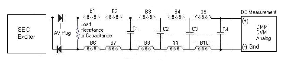
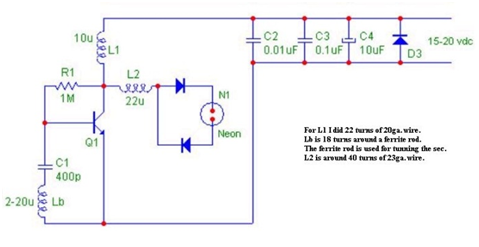
I built the circuit above, the most difficult is the construction of the 3 coils done by hand and checked with the LCR meter. With an input of 10.7 volts, 10 big leds of 3 volts connected in series on the avramenko plug light strongly following a precise adjustment of L1.

On a bandwidth span of 350 Mhz, this little beast is very very rich in harmonics, surprising how it being with this assembly I get 10.3 Mhz of central frequency. Very interesting experiment to do on coils behavior.


With a view on spectrum analyzer (TinySA), harmonics are very present all along the spectrum 

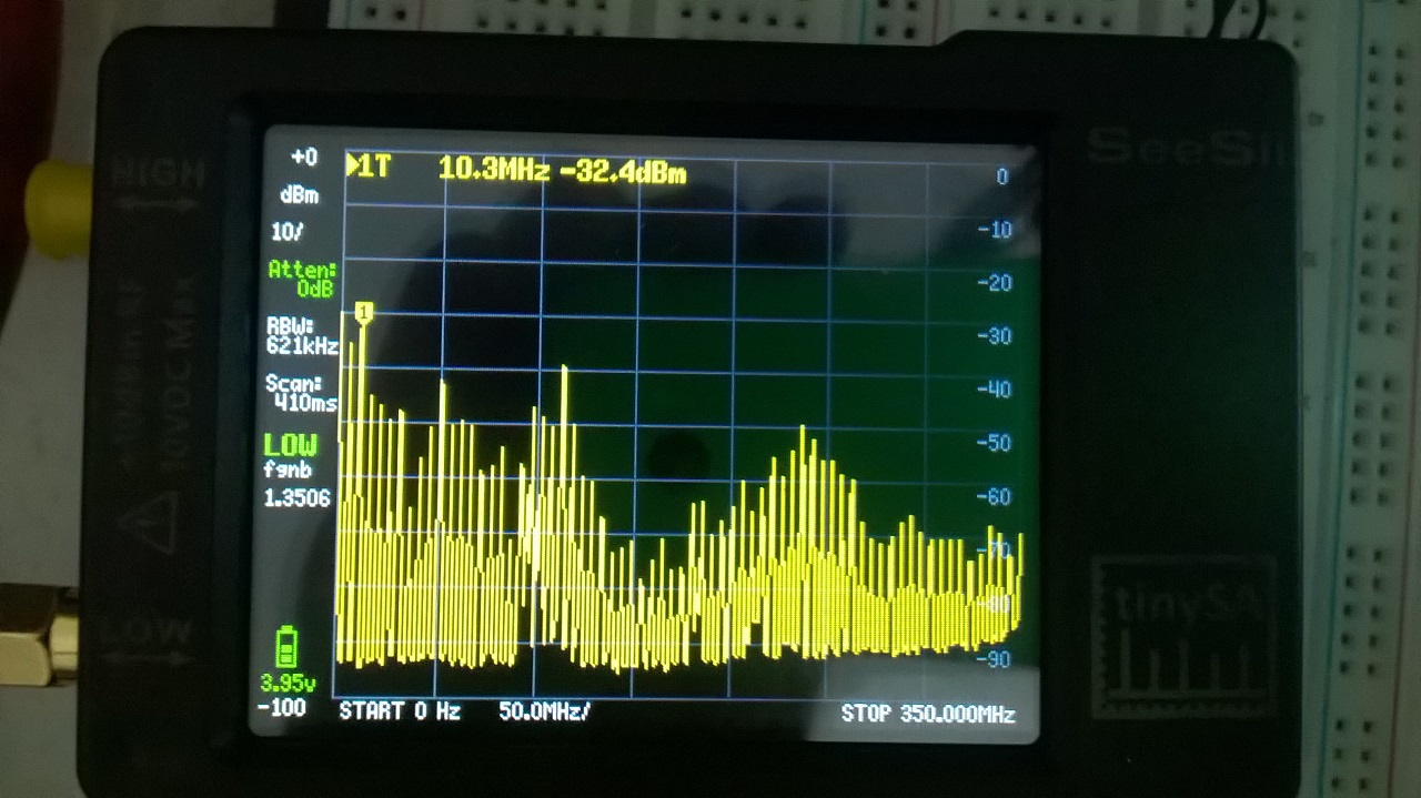
You can see on the Spectrum Analyser a multitude of harmonics produced by spatial coherence at left starting a 0 hertz passing by 10.3Mhz under digit 1 and at right stop at 350Mhz. Resolution bandwith is automatic at 621Khz but i can change to have awider one.

Simply wonderful with lots of energy available.

It seems that this little beast is capable of taking even more. The following will be the addition of an additional load of 10 other LEDs in order to verify the consumption behavior (input power) of the circuit.


Jagau

Shelfordella posted this 14 February 2023

Great work! You could try and see if it influences FM radio, Dr. Stiffler shows in a video that his radio went silent.

"A little theory and calculation would have saved Edison 90 per cent of the labor." Nikola Tesla

Close