
I transferred my thread on Ferro-Magnetic Resonance here to BeyondUnity.org
YoElMiCrO's Ferro-Magnetic Resonance
- 11K Views
- Last Post 25 January 2026
YoElMiCrO
posted this
09 February 2024
I transferred my thread on Ferro-Magnetic Resonance here to BeyondUnity.org
- Liked by
-
-

-

YoElMiCrO
posted this
27 February 2020
Hi everyone.
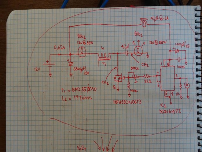
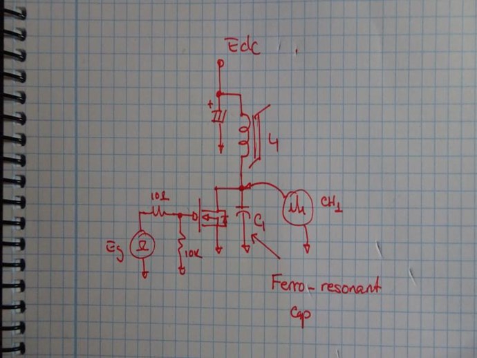
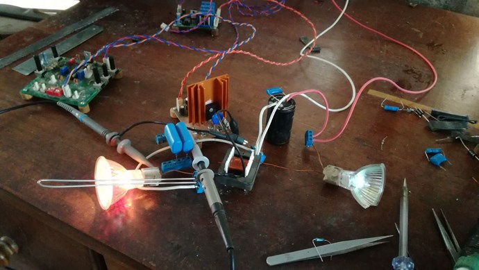
Circuit to check ferro-resonance.
The two bulbs are 12V @ 35Watts, if you want you can do the experiment.
The mosfet can be an IRF3205, anyone with an Rds (on) whose value is at least
the value of the load between 10 so that Norton is negligible.
For example, if the bulb is 35W @ 12V, the minimum resistance of the mosfet in the state
on should be less than (12 ^ 2/35) /10=0.4 Ohm.
As the one I propose has 0.008 Ohm, it will more than meet that load.
With respect to the driver, anyone capable of delivering a peak current of 3A
It will be left over.
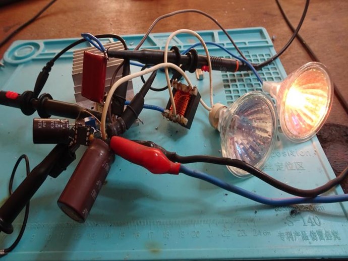
Here the images of the circuit and its tests.
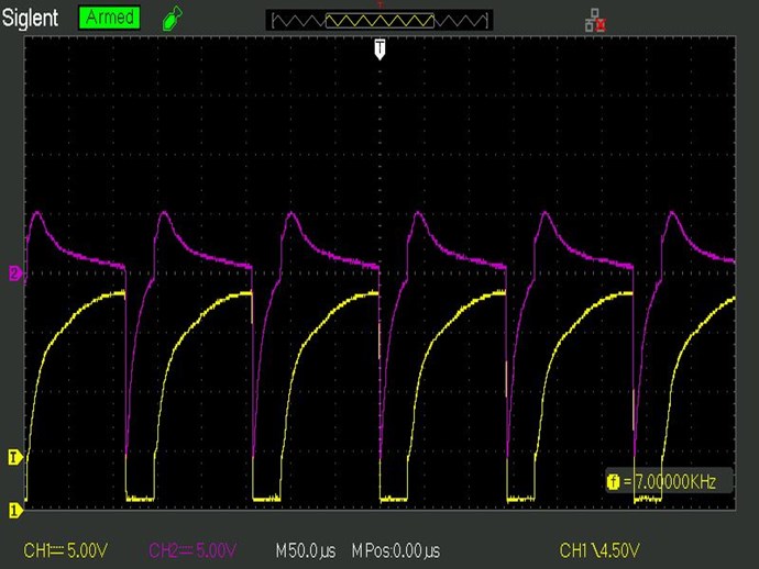
The method of adjustment is as follows.
We apply a pulse of 2uS to the mosfet, at the beginning the 500 Ohm resistor in the gate to the minimum,
with a low frequency, say 100Hz.
We see the response in the waveform applied to the load, we adjust Ton so that
the answer begins at its maximum negative and at the end of Ton touch 0 Vdc.
Then we verify that in drain of the mosfet during the Toff cycle the answer is
ferro-resonant, this means that the first cycle of the sine function is not symmetric.
Then we raise the frequency while keeping Ton constant.
YoElMiCrO.
- Liked by
-
-

Jagau
posted this
27 February 2020
Hi yo
excellent experiment to replicate, which I will do.
So you have to achieve this asymmetry by adjusting the Ton that you adjust by the variable resistance on the gate of the mosfet. After that, you can change the frequency only when you reach the asymmetric point, is that it?
Jagau
What we consider to be empty space is merely a manifestation of unawakened matter. N.T.
- Liked by
-

Vidura
posted this
27 February 2020
Hey Jagau,
I think the Ton has to be adjusted by the signal source, and the 500ohm resistor has the function to control the rise time of the switch.
please correct me if im wrong Yoelmicro.
Vidura.
Vidura
- Liked by
-
YoElMiCrO
posted this
27 February 2020
@Vidura
Yes, that is the funtion of 500 Ohm resistor
- Liked by
-
Jagau
posted this
27 February 2020
Yes, I know that the switching speed, rise time + many other things, of the gate of the mosfet is determined by the gate resistance of the mosfet.
It was for this question, that I did not understand in your explanation given that channel 1 was to stay at 7khz as in your scope shot:
we adjust Ton so that the answer begins at its maximum negative and at the end of Ton touch 0 Vdc
Thanks for the explanation
jagau
What we consider to be empty space is merely a manifestation of unawakened matter. N.T.
- Liked by
-
Jagau
posted this
27 February 2020
Hi yo
I will build the circuit so we can join in our ideas.
Miller capacity , yes maybe. To prevent self turn-on we have to prevent it?
One thing that I understood well with the ferrro-resonance it is very unexpected and it is triggered with a variation in voltage, as at the beginning of the thread, non linear resonance and ferro-resonance are add up in certain case.
Jagau
What we consider to be empty space is merely a manifestation of unawakened matter. N.T.
- Liked by
-
YoElMiCrO
posted this
27 February 2020
Hi everyone.
@Jagau.
I find the idea of joining forces spectacular.
When I talk about the miller effect it is to use it as a capacity coupled to the circuit.
For example…
The capacity that the driver sees from the gate is:
Ct = Ciss + [Crss (1+ (Vds / Vg))]
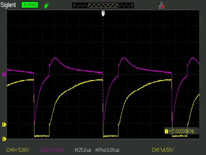
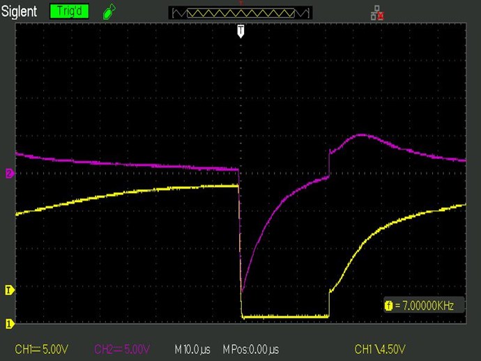
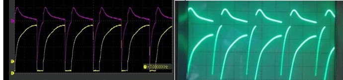
One way to verify the effect of ferro-resonance is this:
What we do is download Cp through Sw then turn it off, now
as the voltage of Cp = 0 and if the value is large enough, it will keep
the voltage at 0V in the drain while growing di / dt to the point where the core saturates.
At that point the current is ahead of the voltage and the voltage in Cp will increase abruptly.
As in the following image.
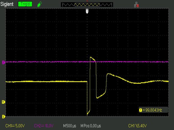
The following oscillations are due to the fact that now Vcp-Edc is not 0 and will take the core out
of saturation until reaching the 3rd quadrant saturating it again and thus the following oscillations.
If you look while the tension falls, the time increases.
Thanks in advance.
YoElMiCrO.
- Liked by
-
-
Jagau
posted this
28 February 2020
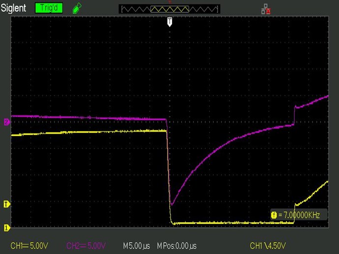
Yes very interesting to see the third quadrant YO
We immediately see an increase in time and thereafter the oscillation with longer time.
Even that we managed to see almost a fourth goes up in the last part. Well done.
It's the simplest things that are the most explicit
Jagau
What we consider to be empty space is merely a manifestation of unawakened matter. N.T.
- Liked by
-
-
Vidura
posted this
28 February 2020
Hey Friends, I did a short test of the circuit, with a CF139 core, the indian cosmoferrite is a cheap material, which has almost cuadratic hysteresis.
I cant do math measurements with my scope, but it looks promising, the effect is there:
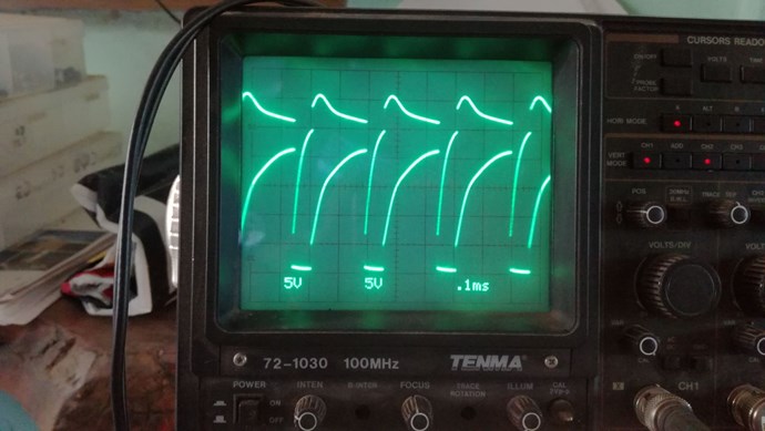
the core becomes very noisy, unless it is pressed together with force.
regards VIDURA.
Vidura
- Liked by
-
-
Jagau
posted this
28 February 2020
yes Vidura
Same effect, you were faster than me
Well done
Jagau
What we consider to be empty space is merely a manifestation of unawakened matter. N.T.
- Liked by
-
-

Support Our Research Platform
Our Beyond-Unity Devices
Members Currently Online:
No one online at the moment
Categories
