AlteredUnity's successful ZPM replication

  • 3.6K Views
  • Last Post 23 October 2023
  • Topic Is Solved
AlteredUnity posted this 16 January 2023

Hey everyone, im glad you started a new community, its a shame your device went from "should be first device to replicate after Non-inductive coil" to a toy, to deleted.

300Turn coil : measurements were made with both coils on center of core at 1khz; Coils were then put at far opposite ends of top and bottom of core.

20awg;  L = 425mH; DCR = 1.73 ohms

150Turn coil : 20awg; L = 110.7mH; DCR = 0.818 ohms

This is a fast trial run, have more to come with some ideas that may improve opperation. With this configureation I still pull 7 watts of power, so there isn't a whole lot of feedback. 

The center tap is connected to cable running to my cars body ground; The scope is connected across load, with its ground on the DRAIN of mosfet. This may be the wrong configuration and reason for not lowering input.

Any pointers are appreciated.

Attached Files

Order By: Standard | Newest | Votes
AlteredUnity posted this 16 January 2023

Hey everyone, im glad you started a new community, its a shame your device went from "should be first device to replicate after Non-inductive coil" to a toy, to deleted.

300Turn coil : measurements were made with both coils on center of core at 1khz; Coils were then put at far opposite ends of top and bottom of core.

20awg;  L = 425mH; DCR = 1.73 ohms

150Turn coil : 20awg; L = 110.7mH; DCR = 0.818 ohms

This is a fast trial run, have more to come with some ideas that may improve opperation. With this configureation I still pull 7 watts of power, so there isn't a whole lot of feedback. 

The center tap is connected to cable running to my cars body ground; The scope is connected across load, with its ground on the DRAIN of mosfet. This may be the wrong configuration and reason for not lowering input.

Any pointers are appreciated.

Attached Files

Fighter posted this 16 January 2023

Hello AlteredUnity and welcome,

Hey everyone, im glad you started a new community, its a shame your device went from "should be first device to replicate after Non-inductive coil" to a toy, to deleted.

Well, there are a very few rational things remaining on the old aboveunity site and there is almost zero real research since we left. The old site is basically dead in the water since then.

We needed to build our new home after that mentally-ill guy started attacking the members of his own team using false accusations and invented reasons, as everyone can see since we left the old aboveunity site became a place of paranoia, lies, disinformation, an religious-like cult with its wannabe cult leader banning "infidels" and preaching the "Bible" of the so-called partnered output coils which is a road going nowhere. What he doesn't realize is the only ones who kept his site advancing and being in top are us, the entire core team of researchers which are now here. You'll find here the entire core team of researchers, former aboveunity members, which are continuing their research and their experiments here.

You can find more details about all these in our public replies (with solid evidences) to his lies and and his false accusations against us here, there are harsh but well deserved words in our replies but the most important there are the proofs we present.

About the deleted ZPM threads, I'll import them in our site as I find time but it will take a while as there is a lot of experiments, tests and data in these threads. Until it's done everyone can download and use the backup archive with the ZPM threads here.

I wasn't aware you're experimenting with ZPM, I'm glad about it, who knows how many researchers are experimenting and replicated it without going public with their replications ?..

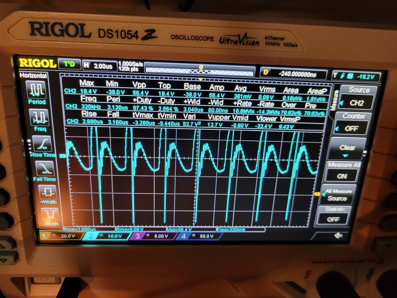
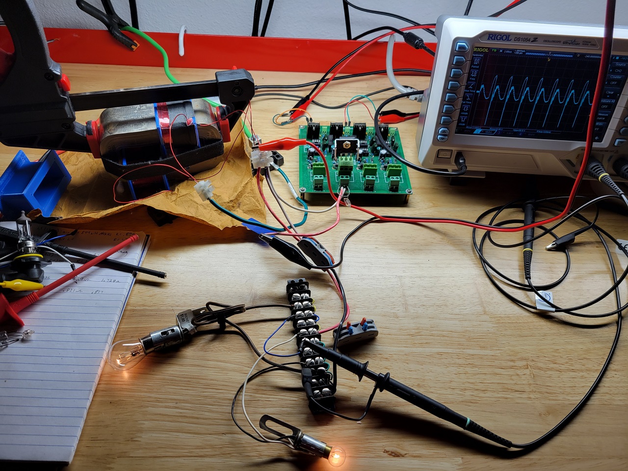
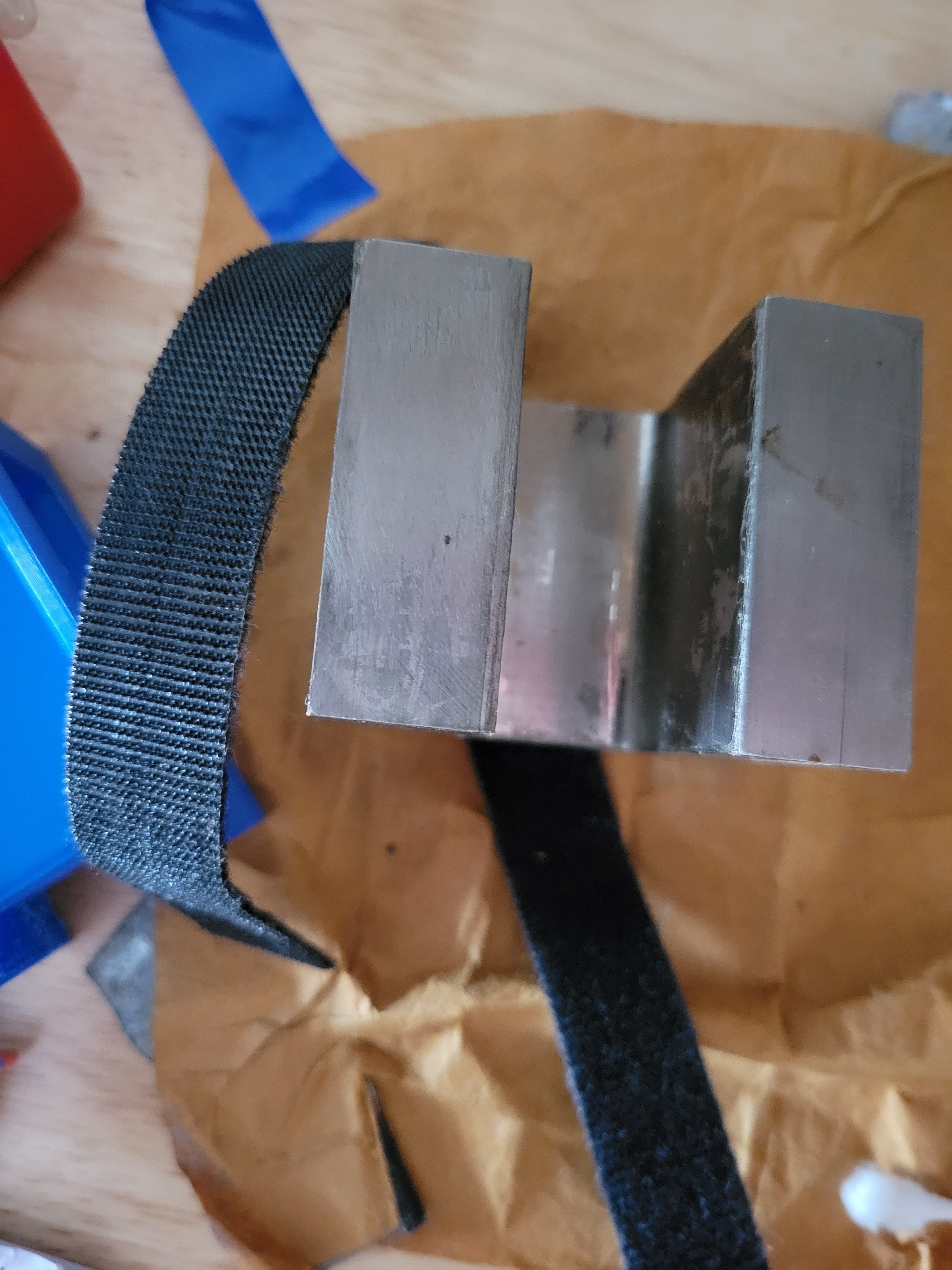
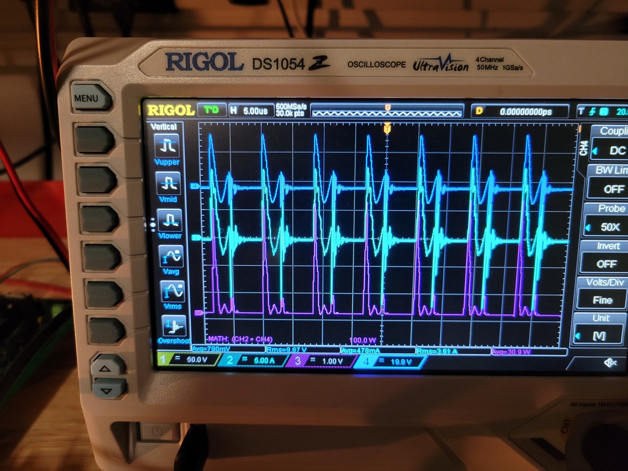
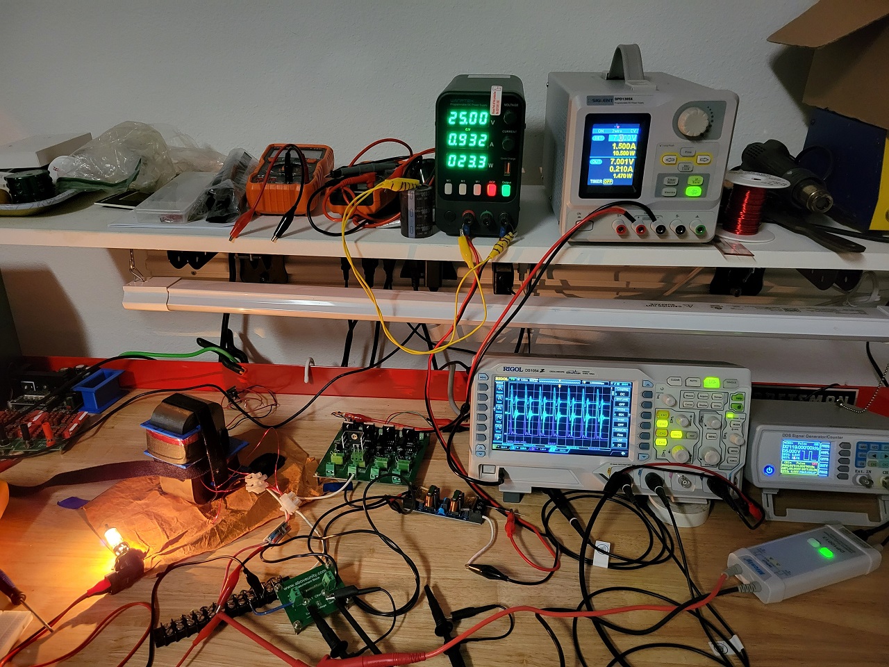
You have a very nice and clean setup there. I see your already have the very familiar ZPM waveform pattern so that tells me you're on the right track with your ZPM replication.

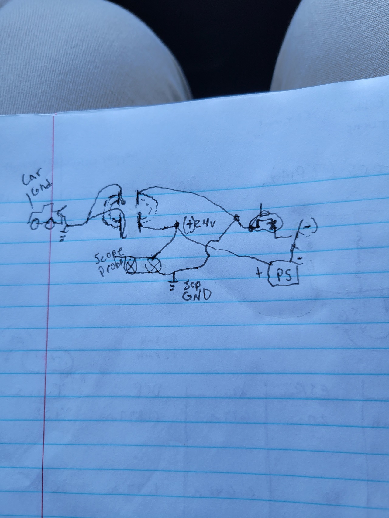
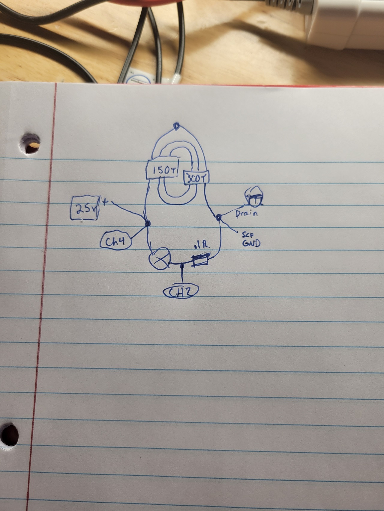
So you don't have the input decreasing effect yet ? Could you present an electronic scheme of how everything is connected in your replication ? Is there a ground connection ? If yes add it to the scheme too.

Since I shown my two ZPMs functioning (the prototype and a replication) there are another three successful ZPM replications: one kept secret for about one year by Chris (you'll find it in the backup archive I specified above) and two new public replications here on our site presented by Atti and Jagau.

So let's try to figure out the cause why the input decreassing effect is not present yet.

Regards,

Fighter

"If you want to find the secrets of the universe, think in terms of energy, frequency and vibration."
Nikola Tesla
Jagau posted this 16 January 2023

Hey alteredunity, welcome

Very nice configuration, just for the purpose of mutual aid I have a question, what formula do you use to get 7 Watts at the input?

Jagau

AlteredUnity posted this 16 January 2023

Thanks for the replies, I am only going off what my power supply is saying when I said 7watts in. Yea took a while to get motivated to make coils, just finished smaller coil yesterday, before that I was using diff bobbin with 150turns, only 1 ground, and it blew my circuit breaker while tuning.(maybe a good sign lol.)
I will post circuit I used for above. I was thinking in order to get coils wire to equal 1/2 the length of the 300 turn I will need to resize the bobbin. Originally I was going to add a 3rd 1/4 turn coil as well. But if the time is taken to do that I wanna get all the wire lengths measured.(I feel like a matching wavelength and divisions of, your coils will probably interact even better.) The center tap is attached to my car for ground.

Jagau posted this 16 January 2023

Remember that what your power supply tells you does not necessarily represent what the circuit consumes. Depending on the duty cycle this can be less than what the circuit actually consumes.
Simplest possible example with a linear resistor with 24 volts on a 10 ohm resistor pulsed at 50% your PS will indicate 26 watts of consumption of the 10 ohm resistor, which is not correct. The correct answer is 13 watts which can be verified in various ways with well-known formulas. The PS does not know the duty cycles, it does not know how to interpret them.
 
For an oscilloscope like you, the calculation is done in IRMS and Vrms, but if you do not have integrated software or purchased separately from your math menu, your oscilloscope cannot interpret the average power, you will not yet have the right answer, it will give you instant power
An oscilloscope without this software calculates the instantaneous power not the average power, don't worry I have the same problem with mine, that's why you have to use the standard formulas.

Jagau

AlteredUnity posted this 16 January 2023

Interesting, thanks for the input. For my oscilloscope Rigol 1054z I have it upgraded with every available upgrades 100mhz etc. - should this mean the values would be correct?(Further testing concludes my oscilloscope does integrate over time and Math(avg) function includes phase shift measurement to give real power of DUT).

With the second ground (to my car) connected to the center tap I will measure input current with scope probe, which should connect my PS (-) to scope gnd as well. Also I will use my differential probe, Jagau recommended to me in past, over my load. Should have pictures of it soon. It may be that 1 of the bobbins are flipped on the core, a reason I don't see the decrease in input as well, just wanted to see the waveform....step 1

AlteredUnity posted this 21 January 2023

Hey everyone, after looking at a few other post I see the potential problem. In Itsu's replication, he and I wrapped coils - 1 cw other ccw -. I have some other bobbins with around 150 turns wrapped the same as my bigger coil, so will try those today while I print another bobbin to redo the 150turn coil. Will hopefully have some results soon. Also, can anyone tell me if the cracks on my core look fine or normal? Will upload photos soon, keep hitting the BeyondUnity link when trying to select photos from phone.

Fighter posted this 22 January 2023

No worries, I downloaded and added the photos in your post.

About the cracks, don't worry, they can appear but their impact on core's characteristics are insignificant.

What I noticed, the lateral surfaces of your core are much smoother than the ones of my cores, seems like they are coated with a metallic layer or something like this. Most likely it's just that coating cracked, not the core itself.

My cores' lateral surfaces are like this, you can actually see the very thin Metglas strips composing them:

Sorry for the quality of the photo, it's taken from an old photo (made in 2017 when I received my Hitachi cores) and zoomed in the part showing one core.

Regards,

Fighter

"If you want to find the secrets of the universe, think in terms of energy, frequency and vibration."
Nikola Tesla
AlteredUnity posted this 22 January 2023

Awesome just checking, this is a Hitachi metglas core from mouser.com. It is so discouraging to think about winding the core as you have yours, considering how OCD I am while winding and the time it'll take. But mean while before winding a bobbin I cannot move, or remove, also your coils are wound in a smaller space thus more magnetic B field so may just resize bobbins. Though currently going to stick with what I have till I can't get better results, thank you for the input.

Fighter posted this 22 January 2023

To be honest at this point there is no data showing the coils should be placed like mine in a ZPM replication.

I mean look at Alnico's successful ZPM replication using a toroidal CRT ferrite yoke core where the coils are near each other.

The reason my ZPM prototype have the coils placed like that is because I developed it based on the configuration of a failed MEG replication. Then I've built my second ZPM (the replica) in the same way just because I wanted to copy exactly the prototype.

So yes, I would say let your coils in the same locations you have them for now...

Fighter

"If you want to find the secrets of the universe, think in terms of energy, frequency and vibration."
Nikola Tesla
AlteredUnity posted this 18 February 2023

Haven't finished winding my secondary coil the correct direction, but had some time to play with my setup. 

It doesn't quite look like the zpm waveform, the pictures are from the output, with .1ohm resistor after load going to drain, and voltage from accross the bulb. Will soon reconnect resistor to measure input, just thought it was good progress, because the input actually drops as I raise the duty cycle, as the output gets brighter(which is sort of counterintuitive). The blue trace(CH4) is voltage across load, teal trace(CH2) is current coming out of bulb into drain, and purple is math CH2xCH4. Load is a 50watt 12v car bulb.

First thoughts are that the duty cycle being raised are allowing the coils to interact better, may take it back down and just increase voltage. Also at most the frequecies that light the bulb i can hear the cores click together. thats why i prefer not to have a clamp holding it. But this is a very interestingconfiguration, thank you fighter for sharing. 119khz with 35% duty cycle


Close