Bi-Toroidal setup/test

  • 4 Views
  • Last Post 1 hour ago
baerndorfer posted this 1 hour ago

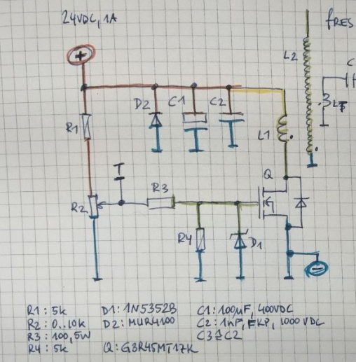
 For this experiment i used a simple analogue pulser as a driver for L1.
my L1 is wound on a special arrangement which you can see in this image..
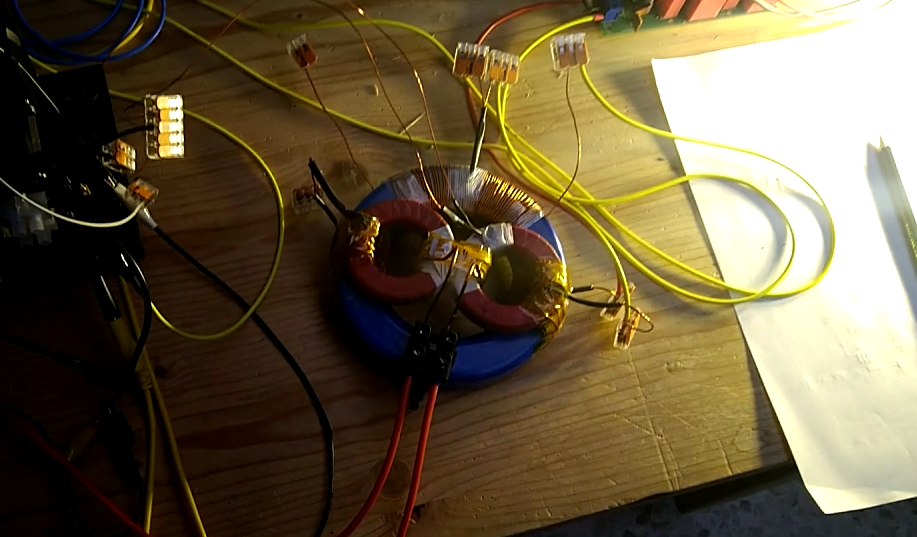
L1 which is 144cm long is in the center (holds 2 smaller toroids). the 2 smaller toroids are mounted on a big toroid with the help of 2 additional windings which you can see on the edges. wire length is 288cm. the winding on the left is 'shorted' and the wwinding on the right side is connected to a diode-plug  the load (3x 100W LED in parallel) are connected to output of diode-plug and receive 26.40V

i use 2.3kV pulses with around 1% (+duty)

this is the FLIR image of this setup under load...
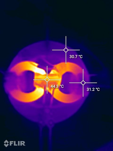
when you watch the video you can see, that the energy which can be extracted from additional output coil do not reflect back in a negative sense. so maybe this is for 'free' to use.

have a nice day

B 

baerndorfer posted this 1 hour ago

 For this experiment i used a simple analogue pulser as a driver for L1.

my L1 is wound on a special arrangement which you can see in this image..

L1 which is 144cm long is in the center (holds 2 smaller toroids). the 2 smaller toroids are mounted on a big toroid with the help of 2 additional windings which you can see on the edges. wire length is 288cm. the winding on the left is 'shorted' and the wwinding on the right side is connected to a diode-plug  the load (3x 100W LED in parallel) are connected to output of diode-plug and receive 26.40V

i use 2.3kV pulses with around 1% (+duty)

this is the FLIR image of this setup under load...

when you watch the video you can see, that the energy which can be extracted from additional output coil do not reflect back in a negative sense. so maybe this is for 'free' to use.

have a nice day

B 

Close