I have tried to replicate the Non-Inductive Coil Experiment. I get similar effects to what Tinker (neale) gets.
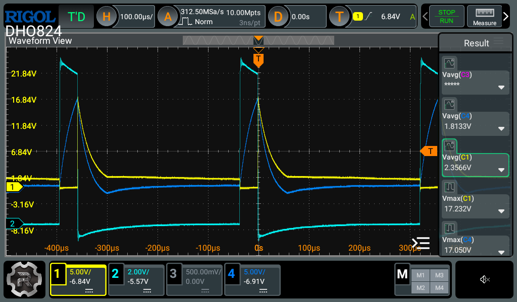
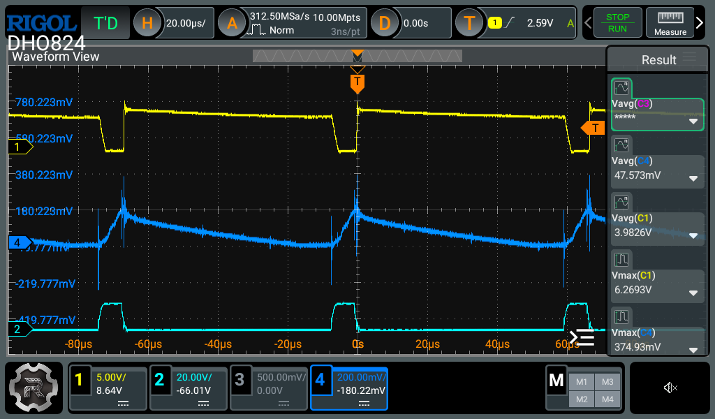
For the wave forms, the saw tooth drops down really fast, so it's for like 70%+ of the time. When I increase the frequency from 3k or so to 12-15k the wave form becomes similar to what's shown in video 7.
I do not have something to measure current right now.
Using amcc0320 Proterial
Primary - cw 14awg ,1.628mm. Wound on top of poc1.
Poc1 - cw 20awg, .813mm
Poc2 - ccw 20awg, 0.813
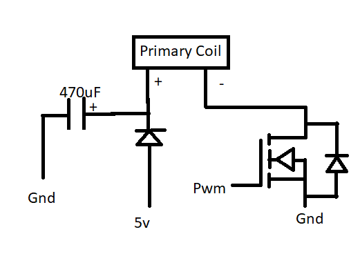
The input are all 5v and the amp shown are the amps on the x-tronic px-70 power supply (linear power supply). The pwm generator is FeelTech fy6300. It is set to 10v ampl and 5v offs square wave (This is to get 0v to 10v square wave pulse). The mosfet used is (IRFP4227PBFXKMA1): https://www.mouser.com/datasheet/2/196/Infineon_IRFI4227_DS_v01_02_EN-1227486.pdf. This has a 21mOhm RdsOn. The signal output from the pwm generator is connected directly to the gate of the mosfet. The primary + is connected directly to the power px-70 power supply. The primary - is connected to the drain of the mosfet. I have a 25v 470uF low impedance capacitor conncted to the priamry + coil and the gnd of the power supply.
One 12v 5w bulb on poc1. Another 12v 5w bulb put on poc2.
I tried to get the peak voltage the same for both poc1, poc2 with the following coils:
22mm wide
primary 7 turns (single layer) (around 13mm wide on top of poc1 about)
poc1 60 (3 layers) turns 21.8mH 1.105uF 0.6ohms
poc2 60 (3 layers) turns 21.8mh 1.138uf 0.6ohms
2800hz 10% 5v .235a poc1: 17.29v peak, 2.33v avg poc2: 17.28v peak, 1.84v avg
22mm wide
primary 7 turns (mutilple layers) (around, 8mm wide on top of poc1 about. I should try to get it closer to 1/4th which is 5.5mm.)
poc1 60 (3 layers) turns 21.8mH
poc2 60 (3 layers) turns 21.8mH
2800hz 10% 5v .238a poc1: 17.77v peak, 2.33v avg poc2: 17.77v peak, 1.74v avg
53mm wide
primary 7 turns
poc1 55 (1 layer) turns 18.28mH
poc2 55 (1 layer) turns 18.33mH
3700hz 10% 5v .195a poc1: 15.4v peak, 1.86v avg poc2: 15.5v peak, 1.57v avg
22mm wide
primary 9 turns
poc1 180 (9 layers) turns 192.5mH
poc2 180 (9 layers) turns 194.0mH
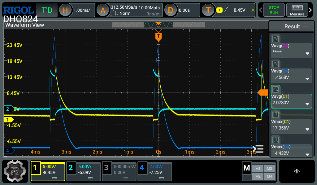
300hz 5% 5v .345a poc1: 18.85v peak, 1.98v avg poc2: 17.36v peak, 1.61v avg
All of these experiments, the sawtooth ended really early (70%+ flat line) before the next pulse.
The lights were mostly the same brightness.
With the 180 turns on the poc, the frequency had to drop really low (300hz), for the peak voltage to be about the same, and the sawtooth ends really fast, so there's a lot of flat time. Also the shorter width coils the frequency had to be lower, for the peak voltage to be the same.
When I raise the frequency, the saw tooth wave form is closer to what tinker and video 7 shows, but poc1 output would increase (4-5v average), and poc2 output would be (200-500mv average).
I am not sure what can be done to get a better sawtooth waveform (going all the way to the next pulse start) and having both poc1 and poc2 output to be close to each other.
I've tried winding primary over both pocs with different number of winds on each poc. I also tried winding the primary over one poc and then switching the direction of the wind before winding over the second poc. The wave forms weren't what was shown in video 7, but I did see in one of the cases both coil would have the same wave sawtooth waveform (like what you get on poc1, where it dips down when pwm rise then spikes up when the pwm falls.) I'm not sure if this is the way to get both pocs to have the same output, but it used a lot more power. One of the combinations of the diodes the output was about the same, the other combinations one was 2x more than the other.
I've tried all 4 combinations of diode direction on both pocs also.
The main thing I want to try and get is to have both pocs have the same output and a good sawtooth waveform (not ending early before next pwm pulse). I might of missed something, but the width of the coil if it's smaller, the magnetic field strength is supposed to increase, which is supposed to increase voltage /current?, but it didn't really increase that much for me with the 60turns (22mm wide, 3 layers) and the 55turns winds (55mm wide, 1 layer). I've tried higher voltages also, but it did not seem to give the result that I wanted (I forgot what the results were). I'm not sure if it's my switching system, but the square wave seemed ok, not super clean. I'll try building the "Quadratron" to see if it makes much of a difference. I think the things that I have left to try is the quadatron, change power supply?, shorten length of wires. Get a better 1/4th width ratio of the primary coil over the secondary. Maybe something is wrong with my core? or try a nanocrystalline core instead of amorphous?
I'll probably try replicating fighter's zpm also, once I understand things more. I've destroyed a 12v sff power supply and a few mosfets so far. I stopped destroying mosfets now, and using the 470uf capacitor the power supply does not go into protection mode? (Clicks and resets back to 5v) anymore and I can increase voltage.