
Hi, here I will share a circuit which gave me great results in various implementations. For sure you all know the selfoscillating ZVS circuits, you can find many of them on YT and the internet. the schematics are mostly similar to this ones below:
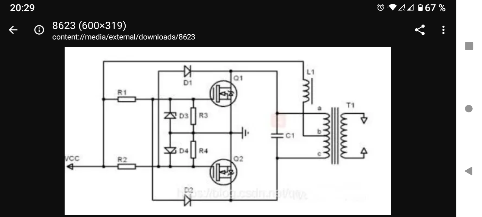
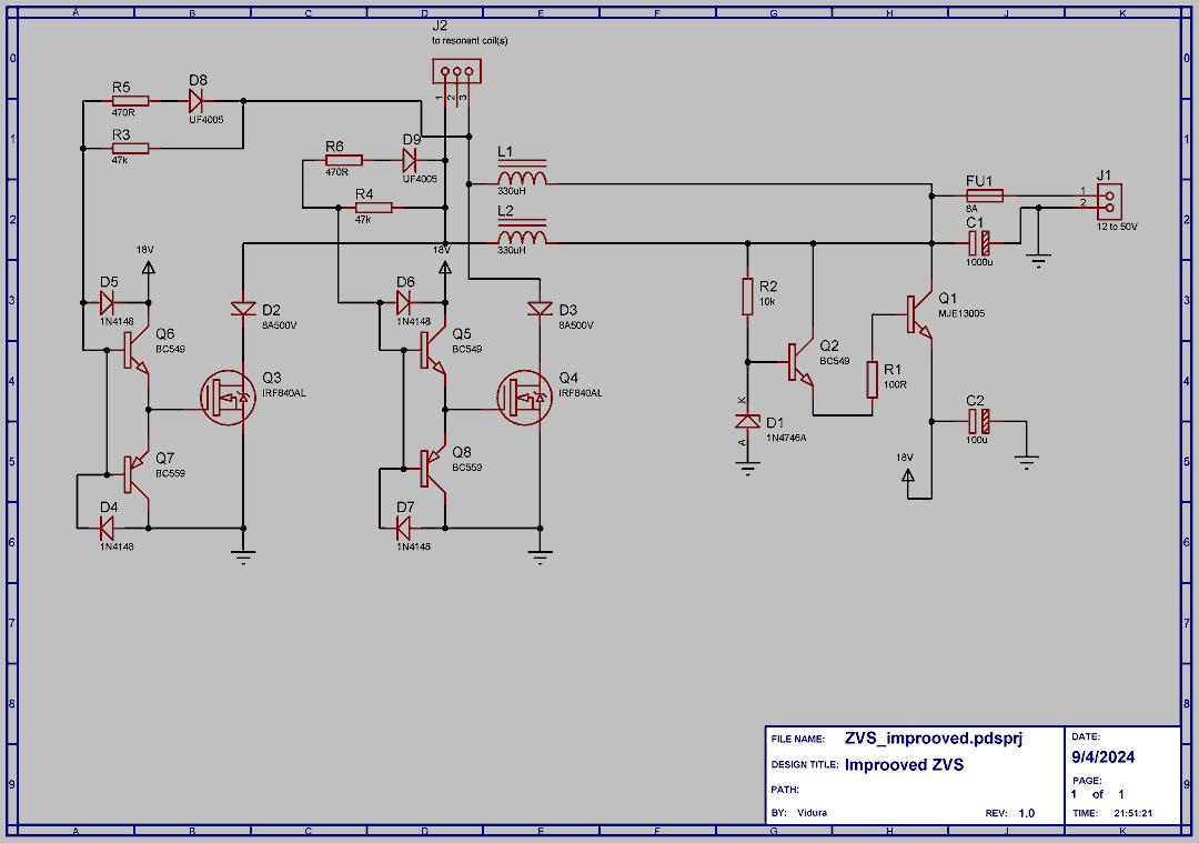
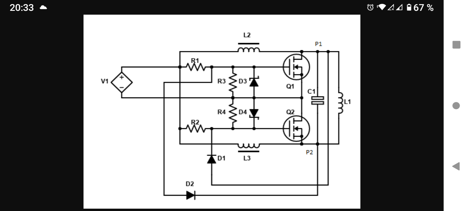 I have tried tham several times in different applications, while used with fixed pareameters and with good primary capacitors they work fairly good. But as I tried with some different kind of resonators, they began to fail. Most comonly the bodydiodes of the mosfet got damaged, or they failed to start oscillating causing losses in components and time, also the pullup resistors of the gates frequently got toasted. The cause as i figured out was the poor gatedrive with this very simplistic circuits. imagine that the gatecapacitance mast charge thru a resistor of tipically some houndreds of ohms. this becomes an issue at high frequencies. So I worked out a different aproach with improoved gate drivers. Also I added a blocking diode to keep the reactive currents away from the mosfet, and a voltageregulator for the drivers to be able to operate at higher voltages.
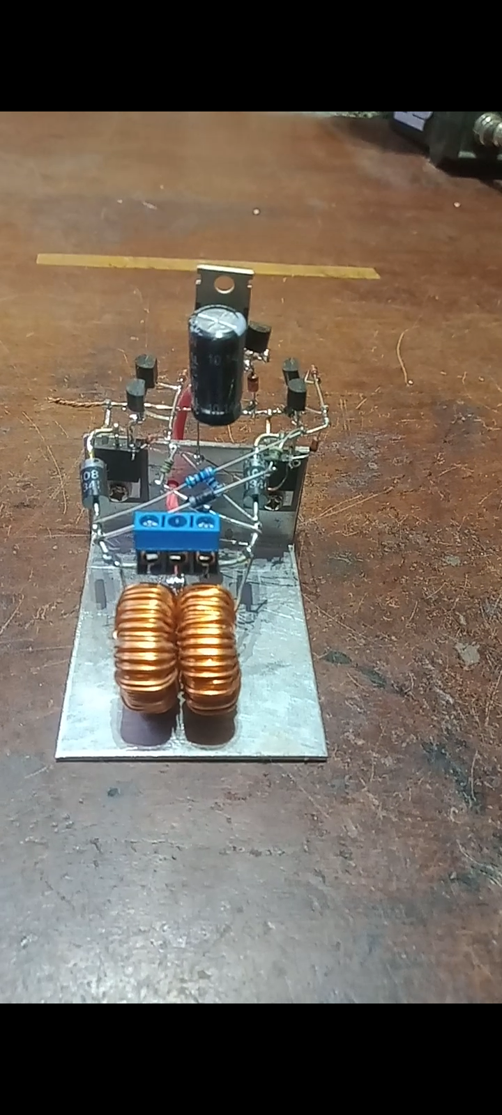
The image below shows one of this improoved circuits:
Here the schematic diagram:
A video with some more information:
Vidura

