
In this thread I will be going through the information provided by YoElMiCrO on ferroresonance.
I will come back and resize the photos if I have time, but want to share my experiences meanwhile.
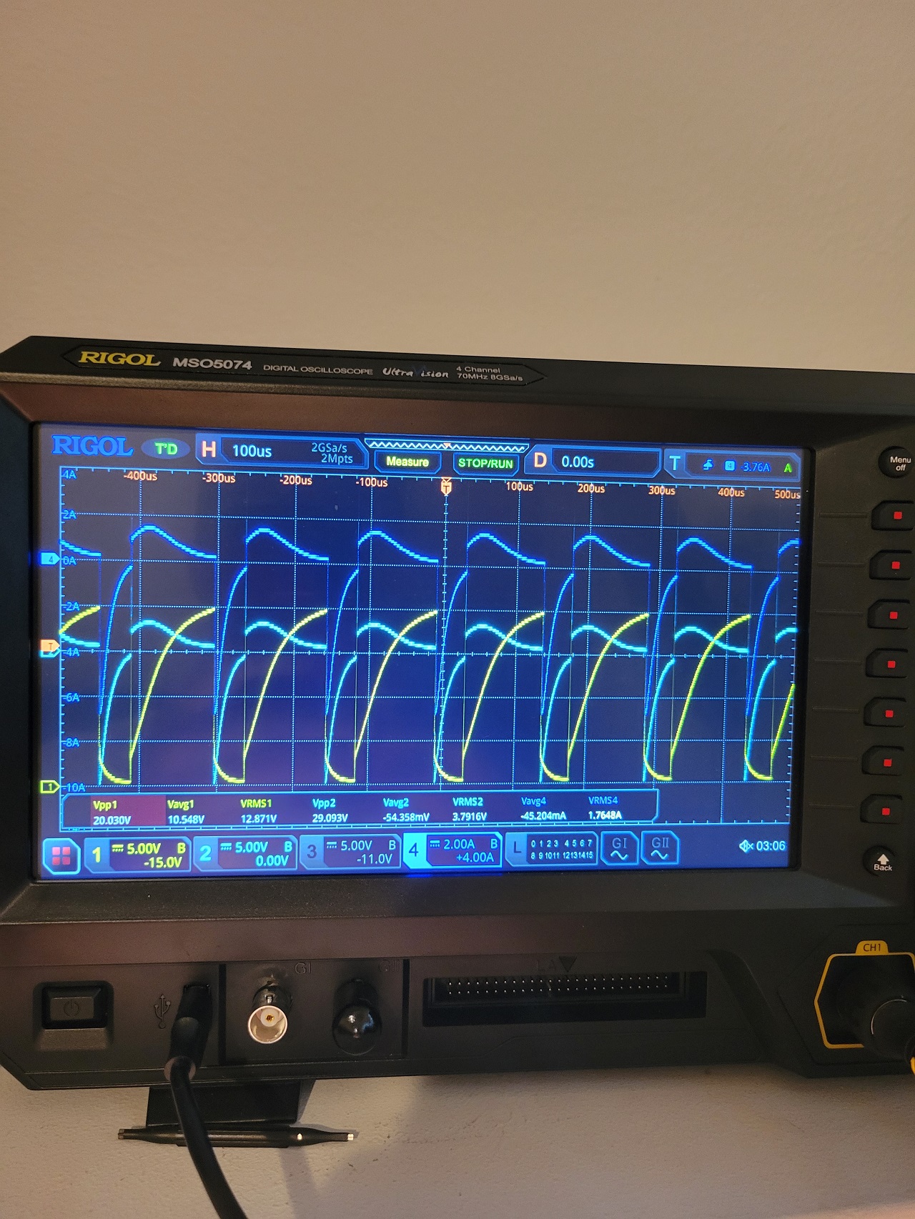
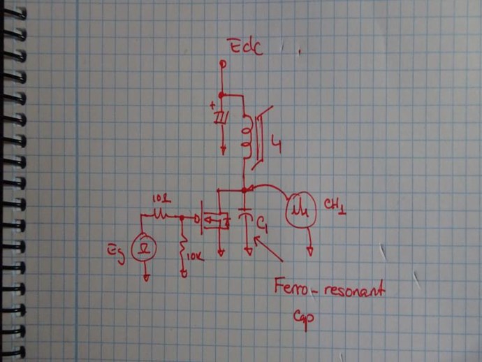
First photo are from the first diagram on YoElMiCrO's thread:
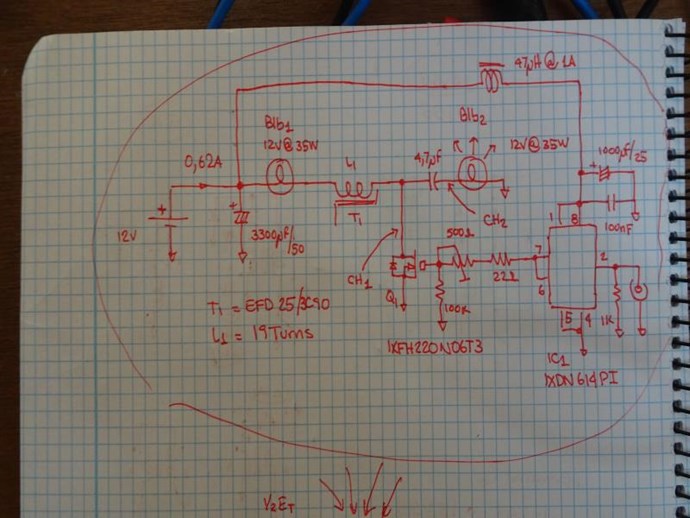
I am using IRF3205, and the gate driver given on the diagram. I wound two transformers on EI33/PC40, I have a few 3c90 cores on their way which should get better results because they have less losses etc. T1 is 16 Turns.
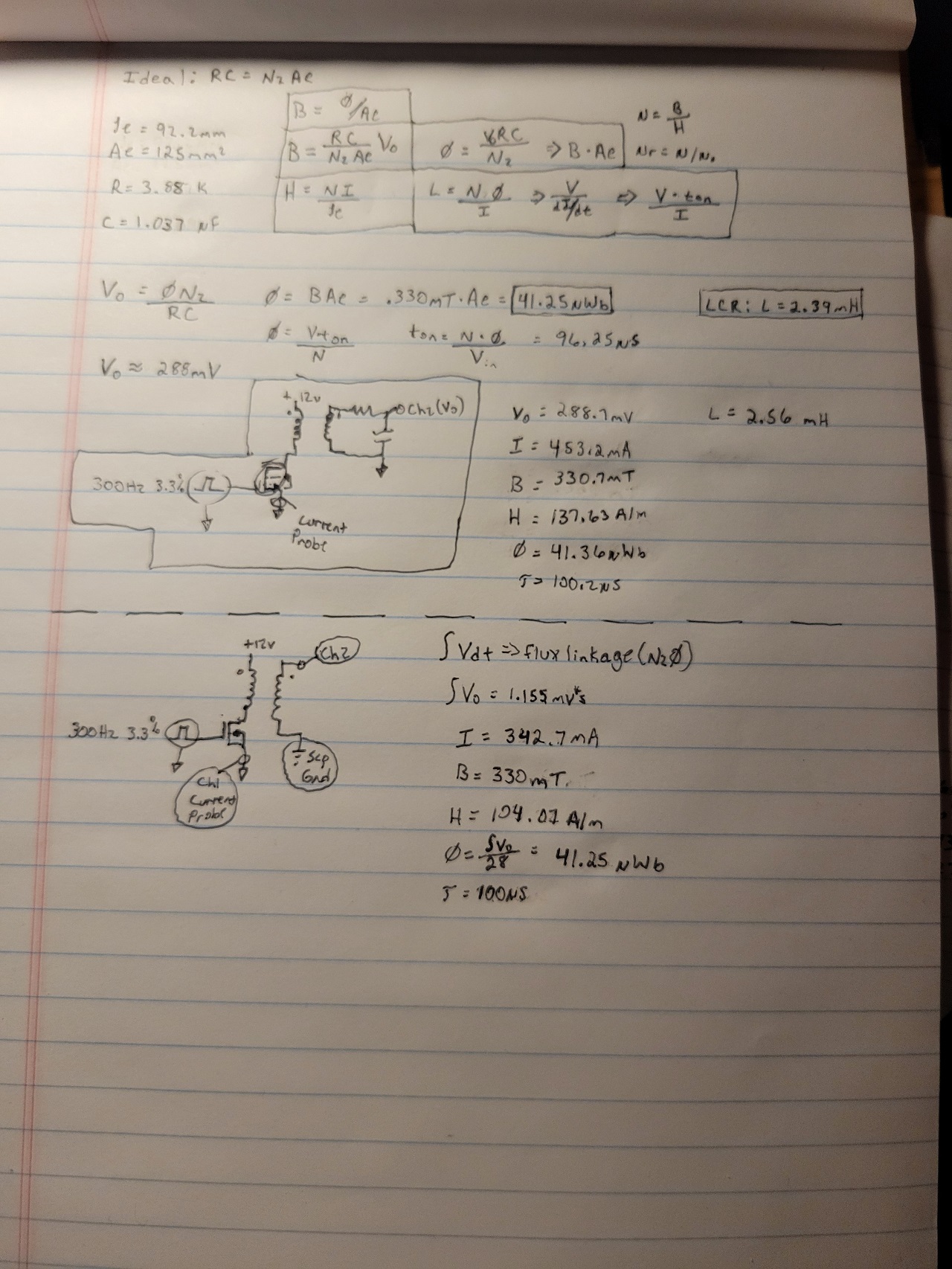
T2 I used the formula provided by YoElMiCrO: N = H(Oe) le(cm) / 0.4*Pi * I = 40 Turns.
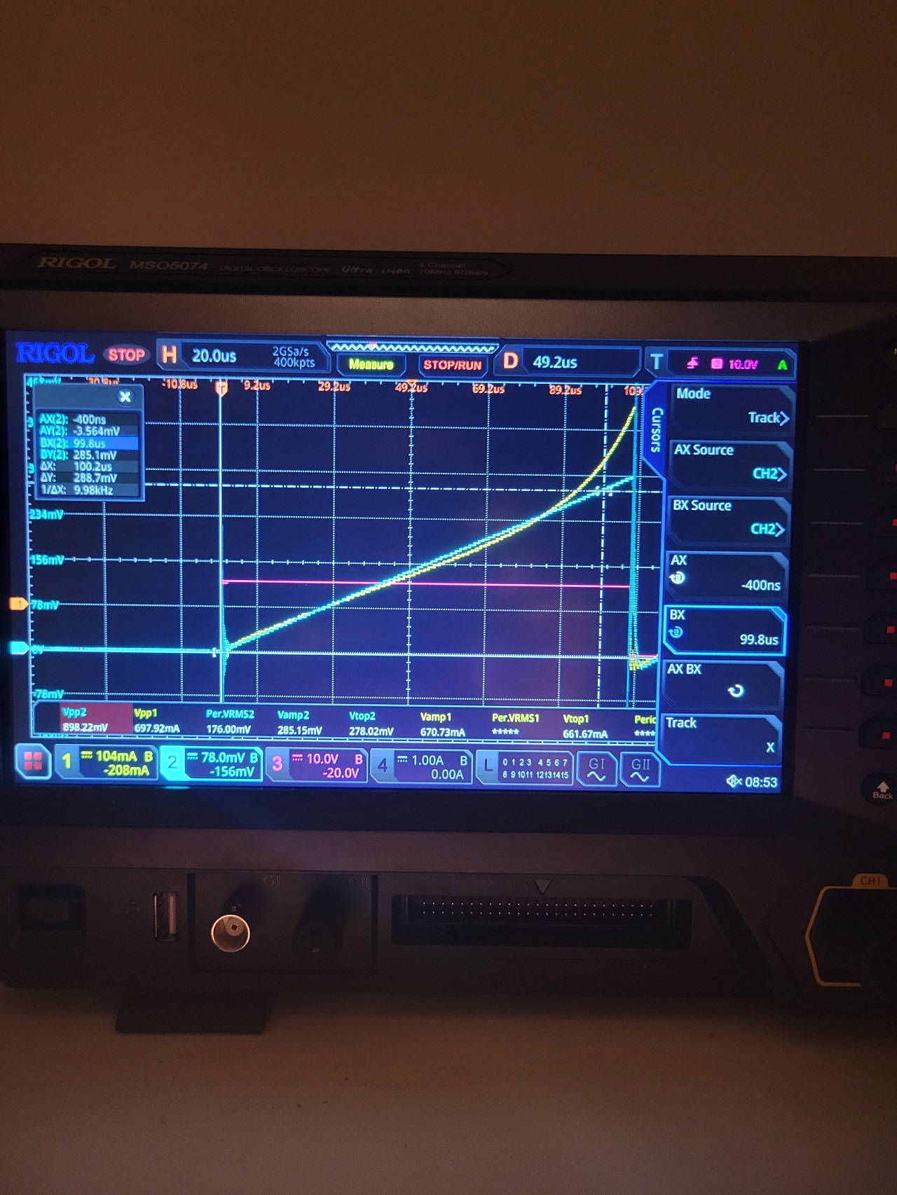
CH1(Yellow/Voltage at Drain), CH2(Teal/Voltage at Bulb), CH3(Pink/Gate), CH4(Blue/Current probe after bulb):
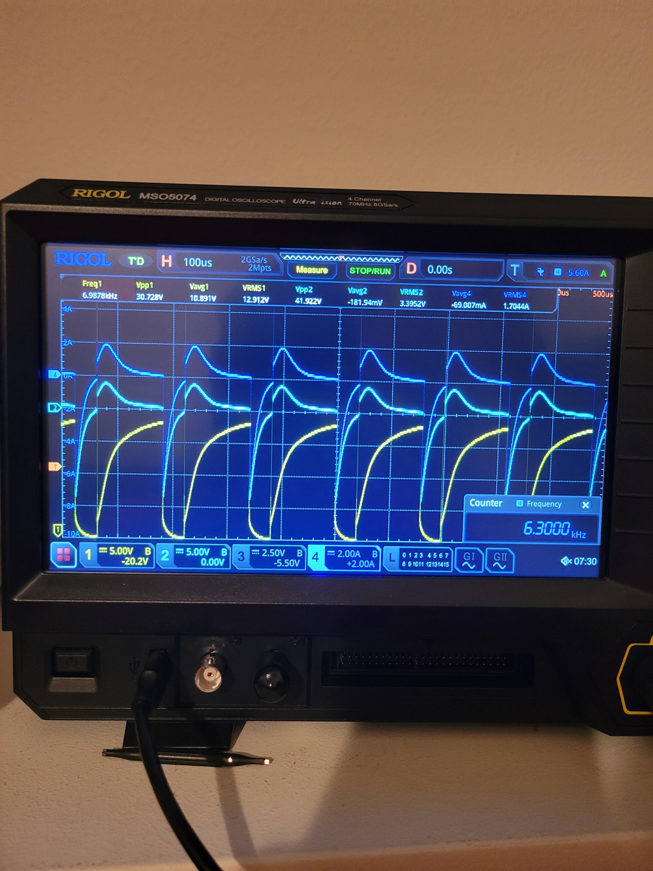
T1 WaveForms:
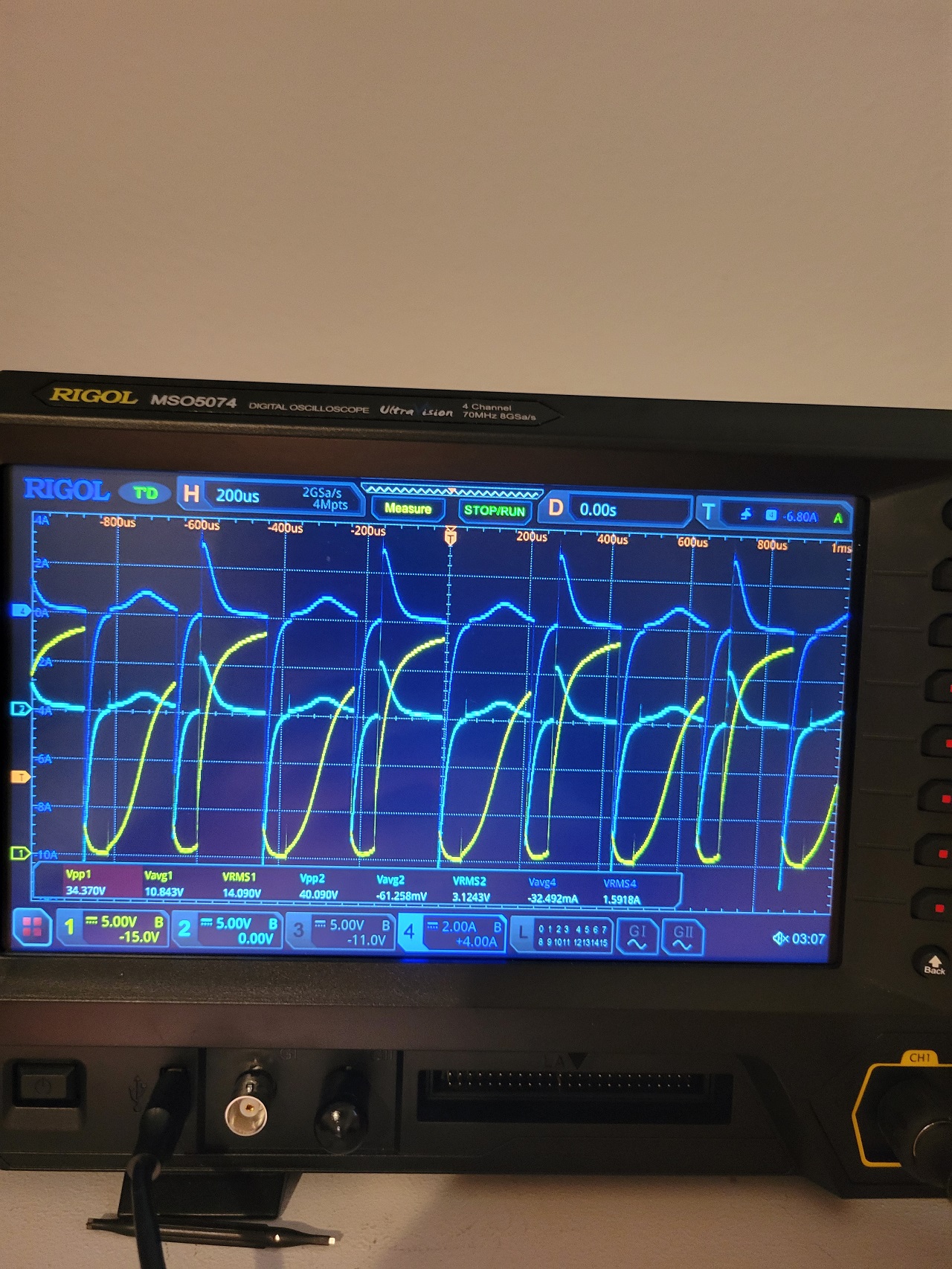
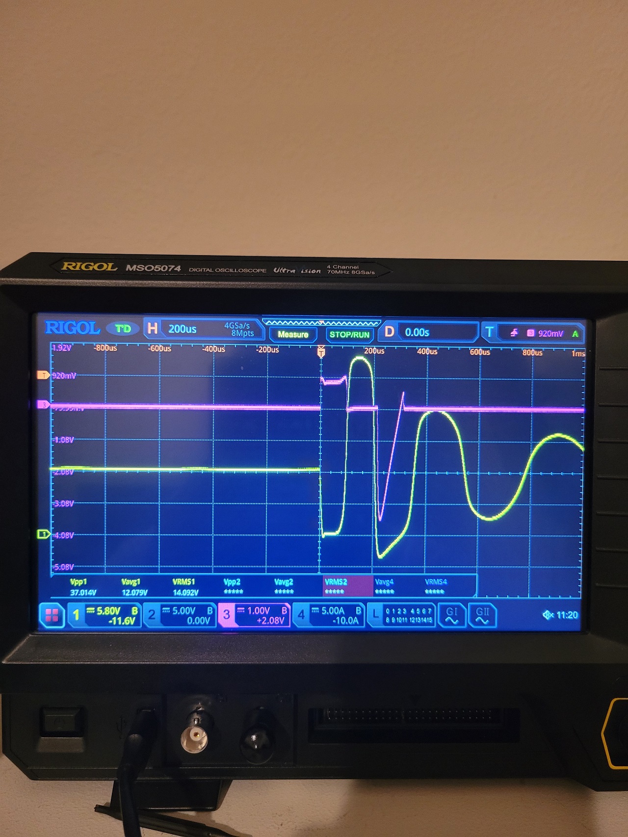
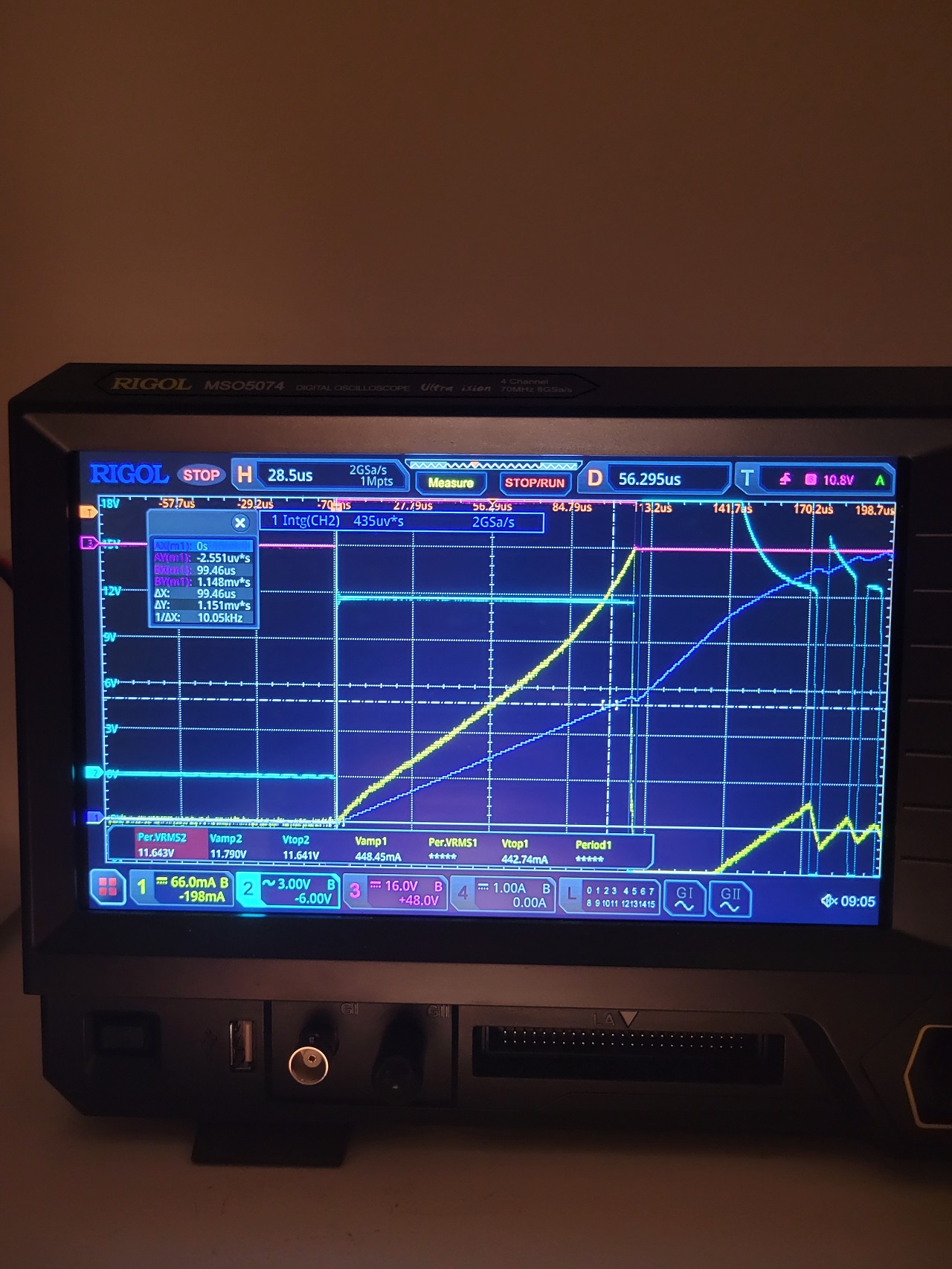
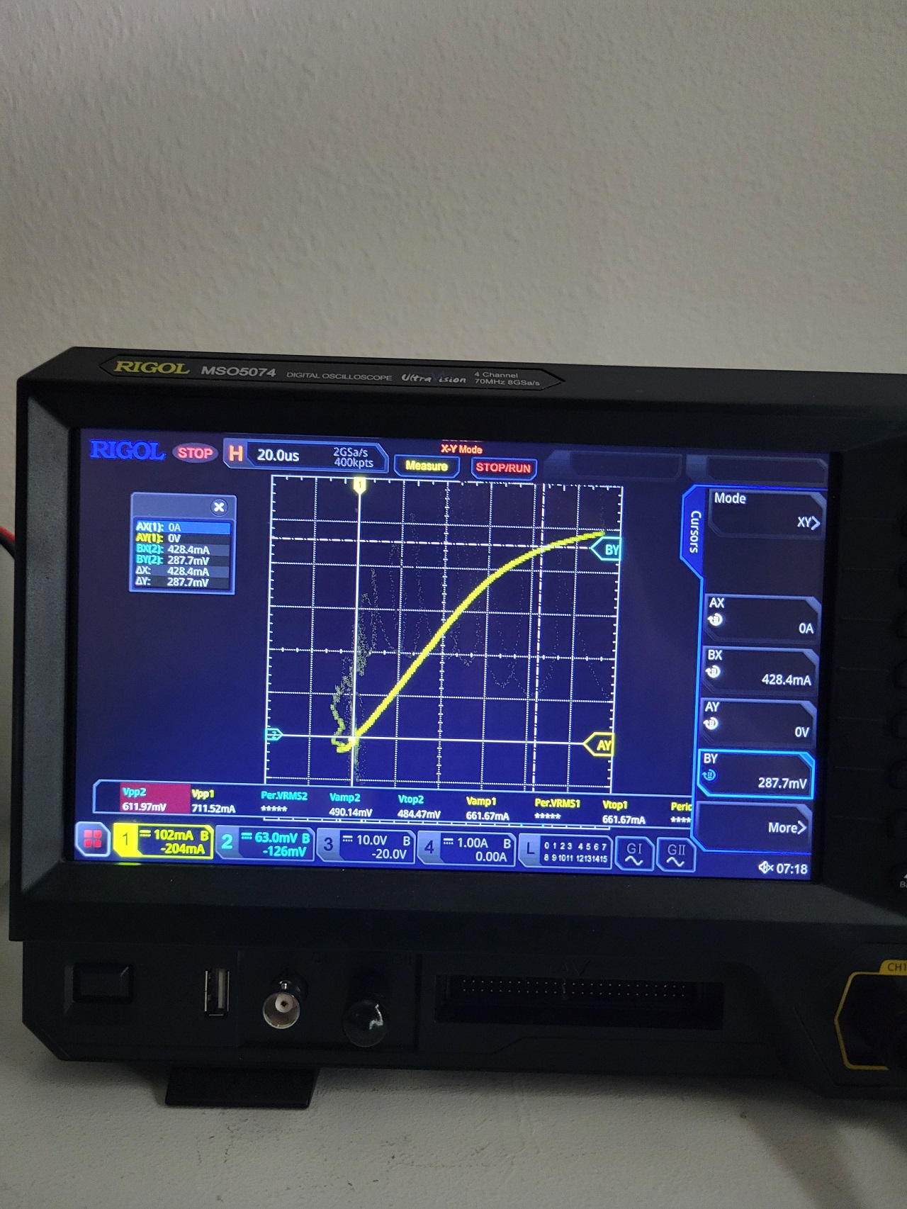
T2(40T) Waveforms: While scanning frequencies, i've came across a point where every other cycle the waveform or reaction changed, at one point you can see the wave roll untill it stablized into the same wave each cycle, shortly after it reverted. Not sure why this is, but heres a couple photos showing what im talking about:
Vidura is correct, everyone should be testing and replicating these simple experiments, and work to grasp an understanding of the complex things going on. Thank you YoElMiCrO for sharing this and providing a path that we can all learn something very valuable.
I already have a PIC programmer, I have more cores, PIC's, and all other IC on the way to continue exploring this phenomenon. Im familiar with C and C++, but will start learning assembly language to be able to configure PIC, hopefully YoElMiCrO may be able to source some code used for this experiment.


.jpg)


