BUNK "OverUnity Transformer" Finally SCHEMATIC and REPLICATION available

  • 6K Views
  • Last Post 4 hours ago
worldcup posted this 4 weeks ago

FInally after many years of long wait and arguments on OU, etc etc bunk decides to release the secrets.. ENJOY (Download video copy / materials before it vanishes from internet) ..Load up your kachers 😀

"Bunk" Kapanadze Variant Device Compilation, Real Deal, With Schematics.. (schematic at end of this video)


Download and mirror as much you guys can from this channel - https://www.youtube.com/@merlit1962/videos

watch all vids from merlit1962, shorts, Posts, Community, there is gold everywhere on his channel. He could have so easily not given us anything, but gave us everything


---

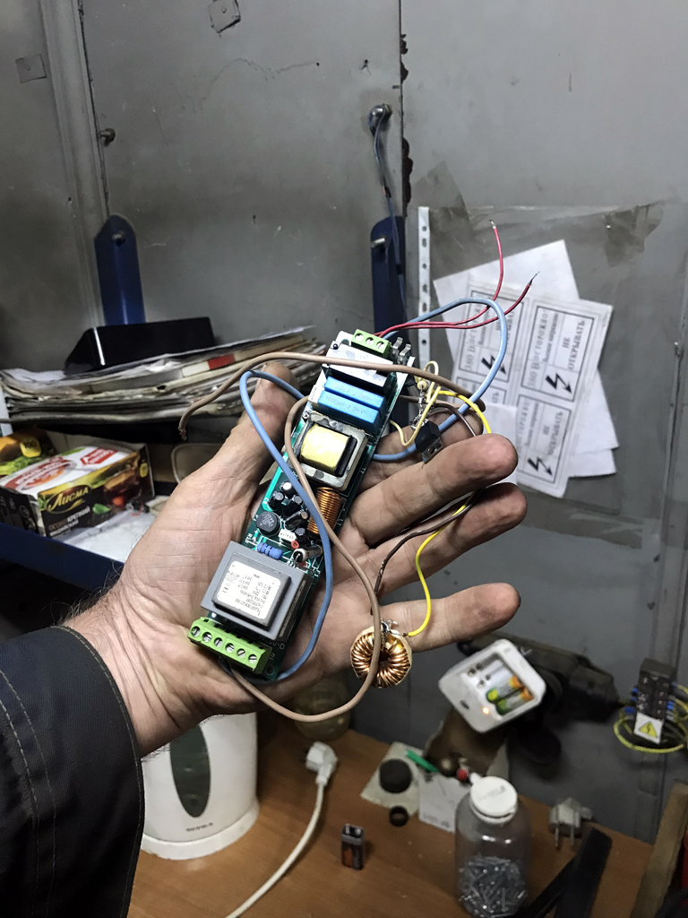
Successful Bunk Replication, within days of released schematics, MerLit1962 MIRROR

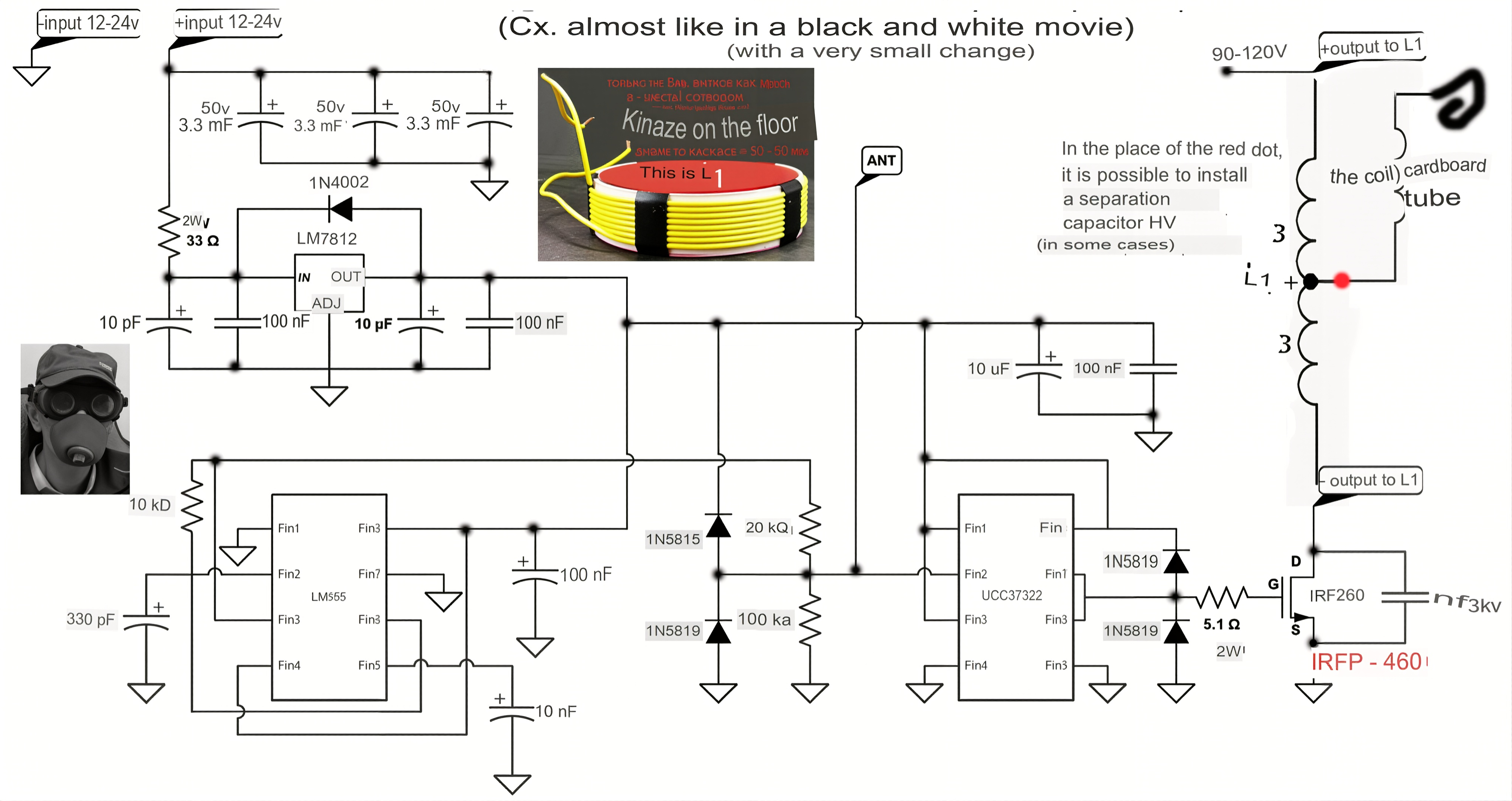
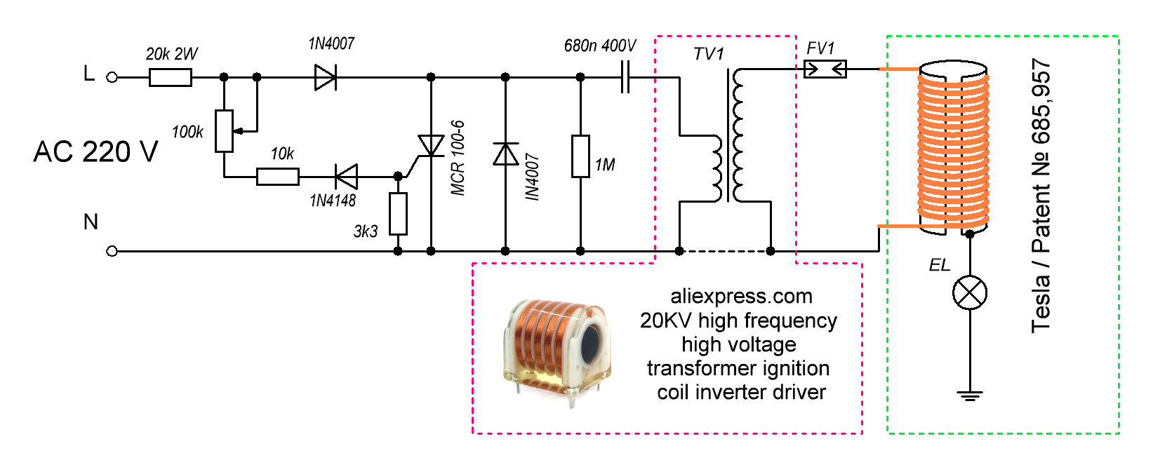
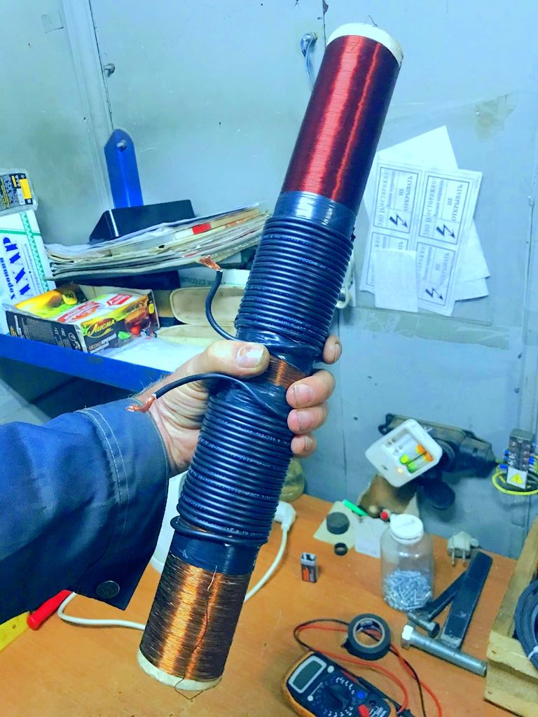
But essentially, it's a relatively small, simplified Kapanadze transformer. The secret is the use of simple aluminum layers inside the coil body, 2 split foils, for both halves of the form, the lower end foil is hit with a certain Positive pulse train, the first winding is held Negative, while the upper foil becomes INTENSELY active, and having an output on the heavy winding. Not a primary to secondary induction, but a rapid changing of voltages between the upper and lower foils, with a 50 hz interruption circuit. Rather than having to move massive currents to induce an output... he is alternating Voltages instead. Bunk has a small transformer like this, doing 4 kw off the 9v. Must see. I will try to upload more too for preservation here.

bunk posted this 10 hours ago

Quoting:Kdkinen kurtsvids

Replying To: bunk

How again was it applied to the aluminum ? as the aluminum is not sticky to keep it. Thank you again.

Hi,

-The Chinese sell good conductive glue! Thanks to them...

forest posted this 7 hours ago

Hello,

The schematic in EasyEda format and the schematic in picture (black&white) looks a little bit different. Which one is correct ?

  • Liked by
  • Fighter
hackoa posted this 7 hours ago

Quoting:forest

Hello,

The schematic in EasyEda format and the schematic in picture (black&white) looks a little bit different. Which one is correct ?

i made it, what is different?

  • Liked by
  • Fighter
forest posted this 6 hours ago

Connection from pin 6 of NE555 is  going to +12V in EasyEda schematic while in schematic from picture it goes to pin 3 (OUT) of NE555. The input voltage is of course not 5V but in range 13 to 24V. The pull down resistor int the line from OUT pin (3) of NE555 just after resistor 20k is 100k in picture while in schematic is 20k.

Capacitor from pin 2 (TRIG) of NE555 should not be 470uF but 470nF like in picture.  I've not checked PCB because I'm not using EasyEda (I use Kicad), but there are some problems there also, mainly the resonant capacitor and track widths are too small in mosfet section (but maybe it's because I imported schematic and pcb into Kicad)

I'm not sure if I spotted all differences, but the main question is which schematic is correct. From my (small) experience and AI chat it seems that original picture (tah one with black&white text) looks like more correct with regulating duty cycle.  it's SSTC schematic with antenna. The second stage I think is how to detect resonant frequnecy and adjust the output capacitor, I hope that is explained in Part 2 video.

Attached Files

  • Liked by
  • hackoa
  • Fighter
bunk posted this 6 hours ago

We have known the "forest" for a long time, here: - www.overunity!......

To avoid unnecessary disputes, I show😋 the original: -

Attached Files

  • Liked by
  • Fighter
bunk posted this 5 hours ago

My student Janis replicated😎 the same circuit: -

Attached Files

  • Liked by
  • Getza
bunk posted this 5 hours ago

My other student makes mercury amalgam like this - I show: -

(Bottom photo, this is a flask with two different electrodes, no mercury filling...)

  • Liked by
  • Fighter
Getza posted this 5 hours ago

Replying To: bunk

well, i try something like this ...., antena( long kabel), i do not have ground, so i use long kabel, lamp shine not at full brightness , consummation goes from 0,4A to 0,8A.

https://www.youtube.com/shorts/zHPZK4gOqAo

IT'S RIGHT THERE IN FRONT OF YOUR EYES! John BEDINI

  • Liked by
  • Jagau
  • Fighter
zaxtone posted this 4 hours ago

Avalanche effect - increase 😉  

  • Liked by
  • Fighter
Close