Clemente Figueras Generator

  • 3.3K Views
  • Last Post 4 weeks ago
Vidura posted this 17 April 2024

Clemente Figueras Generator

Searching for the principles.

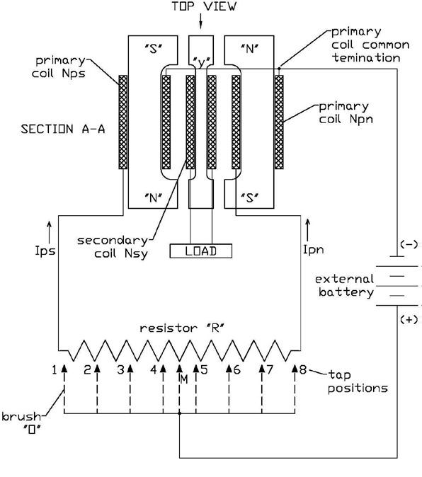
There was the Clemente Figueras thread on the AU forum many years ago, which I followed with great interest. Several talented builders were showing their skills and ideas. What was notable in my opinion, that all of them were convinced to know how it supposedly works and thus following more or less the same line. Eventually I have been scolded for proposing a different idea. The reason why different options should be explored is quite obvious: if it could not be replicated relaying on these ideas in 120 years, there could be a mistake in the interpretation of the patents. It is known that from the patent scripts several drawings had disappeared. It seems the only remaining is this block diagram:

The comments translated to English have of course been added by someone. Figueras himself never referred to the coil sets as “primary “ or “secondary” coils. He always described his machine as a generator and not as a transformer. What is the most important difference between them? On the internet we can find some answers, although doubtful ones. For example, that mechanical energy is converted into electricity in a generator, and that the changing magnetic field in the transformer induces a voltage in the secondary. The output voltage on the windings of the generator is not proportional to the number of turns ratio between the excitermagnets and the output winding. it is dependent on the magnetic field strenght, the rate of change per time unit and the number of turna on the outputwindings. I will come back to this later why I called doubtful such explanations. The most important difference is that the exciter magnet in the generator is continuously magnetized in the same polarity in contrast to the transformers primary. In this thread I will propose and test some different approaches to find the magic in this machine.

If we read the patents, it is quite straightforward explained how the machine resembles the operation of a standard generator or alternator without moving coils or other parts, with exception of the switching mechanism with brushes and a dc motor. But there is not one hint about how the reaction as per Lenz’ law is avoided. It is not too difficult to build a solid-state generator with a good efficiency. When I experimented with the DZ generator with rotating magnetic fields, I came to 95%+ but unfortunately not over 100%. This would be only possible by diminishing or cancelling the Lenz’ reaction. The numerous experiments I performed pointed to this direction.

So I will conclude this introduction with the statement: if we don’t understand how it works we cant likely reproduce it. And even if someone succeeds by trial and error without understanding how, it is not likely replicable for others. This applies for other inventions and devices as well.

will continue soon 

Vidura

Order By: Standard | Newest | Votes
Vidura posted this 17 April 2024

Clemente Figueras Generator

Searching for the principles.

There was the Clemente Figueras thread on the AU forum many years ago, which I followed with great interest. Several talented builders were showing their skills and ideas. What was notable in my opinion, that all of them were convinced to know how it supposedly works and thus following more or less the same line. Eventually I have been scolded for proposing a different idea. The reason why different options should be explored is quite obvious: if it could not be replicated relaying on these ideas in 120 years, there could be a mistake in the interpretation of the patents. It is known that from the patent scripts several drawings had disappeared. It seems the only remaining is this block diagram:

The comments translated to English have of course been added by someone. Figueras himself never referred to the coil sets as “primary “ or “secondary” coils. He always described his machine as a generator and not as a transformer. What is the most important difference between them? On the internet we can find some answers, although doubtful ones. For example, that mechanical energy is converted into electricity in a generator, and that the changing magnetic field in the transformer induces a voltage in the secondary. The output voltage on the windings of the generator is not proportional to the number of turns ratio between the excitermagnets and the output winding. it is dependent on the magnetic field strenght, the rate of change per time unit and the number of turna on the outputwindings. I will come back to this later why I called doubtful such explanations. The most important difference is that the exciter magnet in the generator is continuously magnetized in the same polarity in contrast to the transformers primary. In this thread I will propose and test some different approaches to find the magic in this machine.

If we read the patents, it is quite straightforward explained how the machine resembles the operation of a standard generator or alternator without moving coils or other parts, with exception of the switching mechanism with brushes and a dc motor. But there is not one hint about how the reaction as per Lenz’ law is avoided. It is not too difficult to build a solid-state generator with a good efficiency. When I experimented with the DZ generator with rotating magnetic fields, I came to 95%+ but unfortunately not over 100%. This would be only possible by diminishing or cancelling the Lenz’ reaction. The numerous experiments I performed pointed to this direction.

So I will conclude this introduction with the statement: if we don’t understand how it works we cant likely reproduce it. And even if someone succeeds by trial and error without understanding how, it is not likely replicable for others. This applies for other inventions and devices as well.

will continue soon 

Vidura
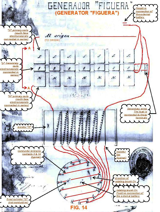
Vidura posted this 17 April 2024

Regarding the information contained in the patents, it might be to a good extent accurate, in context with the understanding of physics of this time. The Autor reiterated many times the similarity with the conventional generator. I also encouraged in other threads the importance of understanding the principles involved in these. And think really deeply about it, try to visualize the spinning alternator and how the magnets turn and the current is induced. The maximum of the induced current is at the moment when the magnetic flux reaches zero. Why? Not reciting to the formula of d/phi-d/t, but very practically and intuitively. If we take a snapshot at the moment of the maximal current, the magnetic poles N and S are located perpendicular to the output winding. They are actually cancelling out each other leaving a net magnetic flux of zero in the output core. But why the current is at maximum? Is there another field which we don’t know about and which actually causes the induction? If yes, what are the properties of this field, can we detect or measure it by any means? If no, how is it possible that the magnetic vector field induces the maximum value when it is not there, and the output dropped to zero when the magnetisation of the output coil is at maximum? I think these questions are at least valid and it makes some sense to think about it.

Vidura

Atti posted this 17 April 2024

 If no, how is it possible that the magnetic vector field induces the maximum value when it is not there, and the output dropped to zero when the magnetisation of the output coil is at maximum? I think these questions are at least valid and it makes some sense to think about it.

Hi Vidura.


These are the very questions that led this person to his experiments. It didn't just happen. (from 1:28)

I repeated it in my own way. But maybe others remember it (if not, that's your problem) and I've already shown implementations. Mostly I followed up the questions,or answers in the "energy reflection" question circle I posted on youtube. Note. Complementing each other,but each theory is worth as much as it can be answered in practice. Especially if we say: free energy.

 If there are no practical answers, then we are left with fiction. 
But let's still strive for a solution!

This applies to all subjects.  Thank you. Atti.


Vidura posted this 17 April 2024

Replying To: Atti

Hi Atti, it is a bit difficult for me to understand and translate videos and I didn’t know about the question circle on tour YT channel. Therefore, I apologize if I missed something. I will only ask you one question: Could you from your experiments get some conclusion if another magnetic field exists, which is not the magnetic vector? The introduction of the thread is only meant to explain some hypothetical background, based on which I planned some experiments to be shown in further posts. 

Vidura

Vidura posted this 18 April 2024

So, I will continue with the subject: 

The inconvenience of the missing drawings in my opinion misled many people who intended to replicate the machine. It seems that many of them assumed that the only remaining sheet was showing the complete physical layout. I will give you an example as analogy: 


If someone never saw a car, he doesn’t know what it is and you show him the image below, he would likely think that it has two wheels:

In contrast with a drawing showing views from different sides it becomes much more understandable how the whole thing looks like:

There was a member of another forum with identity Wonju Bajac I think, who proposed the following sideview of the coil arrangement:

It was stated that he tested this version and did not get COP>1, but I have no information about the parameters and used components. I don’t think that this was exactly the arrangement which was used by Figueras, but anyway, I believe that his thoughts went in the right direction. It would be straightforward to use closed magnetic paths with minimal gaps to build an efficient generator, or an efficient electromagnet by using both magnetic poles. 

In a conventional generator built with silicon steel sheets as cores we would use for the exciter magnet a magnetic field strength of 1T or a bit more for full load condition, leaving some safety margin to the saturation value near 2T. 

There are two more details which according to my current hypothesis should be taken in account: the original machine used likely the wire wound resistor array, and this was not an inductor as many replicators though.  The reasoning behind this was usually that inductors are much more energy efficient as current regulators than resistors. Correct, but energy efficiency is not a concern for the exciter magnets, as they usually consume only a small percentage of the output power. And moreover, I am convinced that the resistors are necessary to reduce the Lenz’ reaction. Of course this has to be proved experimentally. I will come back to this and explain the idea. The other detail are the mechanical brushes described in the patent. If we use this technology, we have to be aware that it requires very precise and neat construction, if it should run for an extended time. It should be possible to replace with solid state switches, I will use bidirectional solid-state relays with mosfet switches for my experiments. Bidirectional, as it might be required to conduce inverted currents in closed state. For the moment I am not sure about this, but anyway it will not hurt to have the same properties as the brush contacts.

Vidura

Vidura posted this 18 April 2024

As I have the parts from the DZ generator experiments, they will be reused for the actual project. By the way It is very likely that the same physical principles apply, I have paused the DZ replication case of missing resources to build new cores and windings. But from the results led me back to the original Figueras Generator (as I imagine it). It should be much simpler than working with the rotating fields of the DZ.

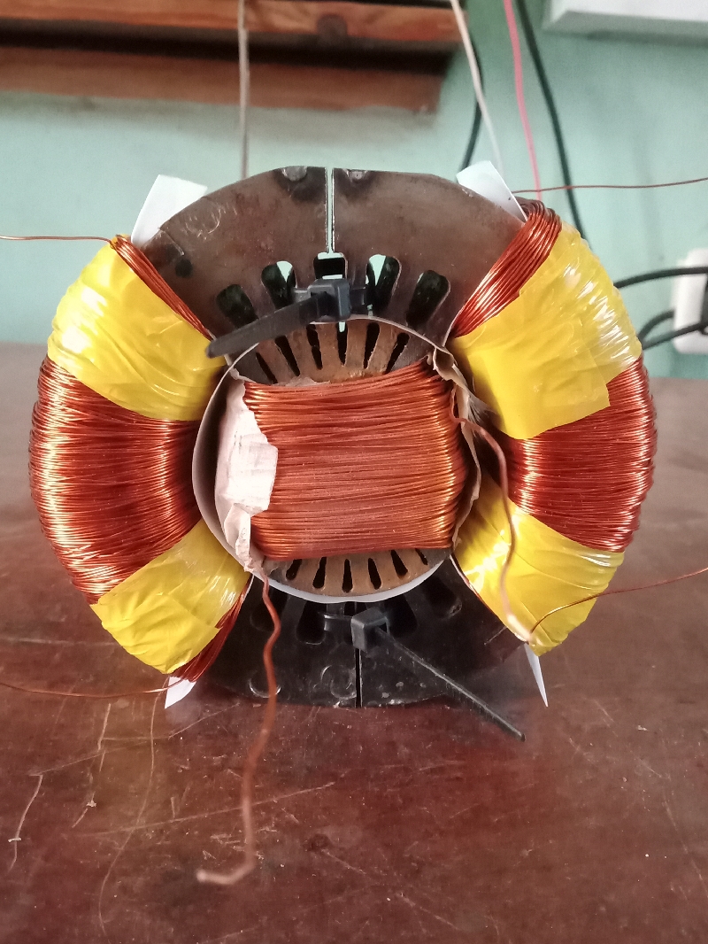
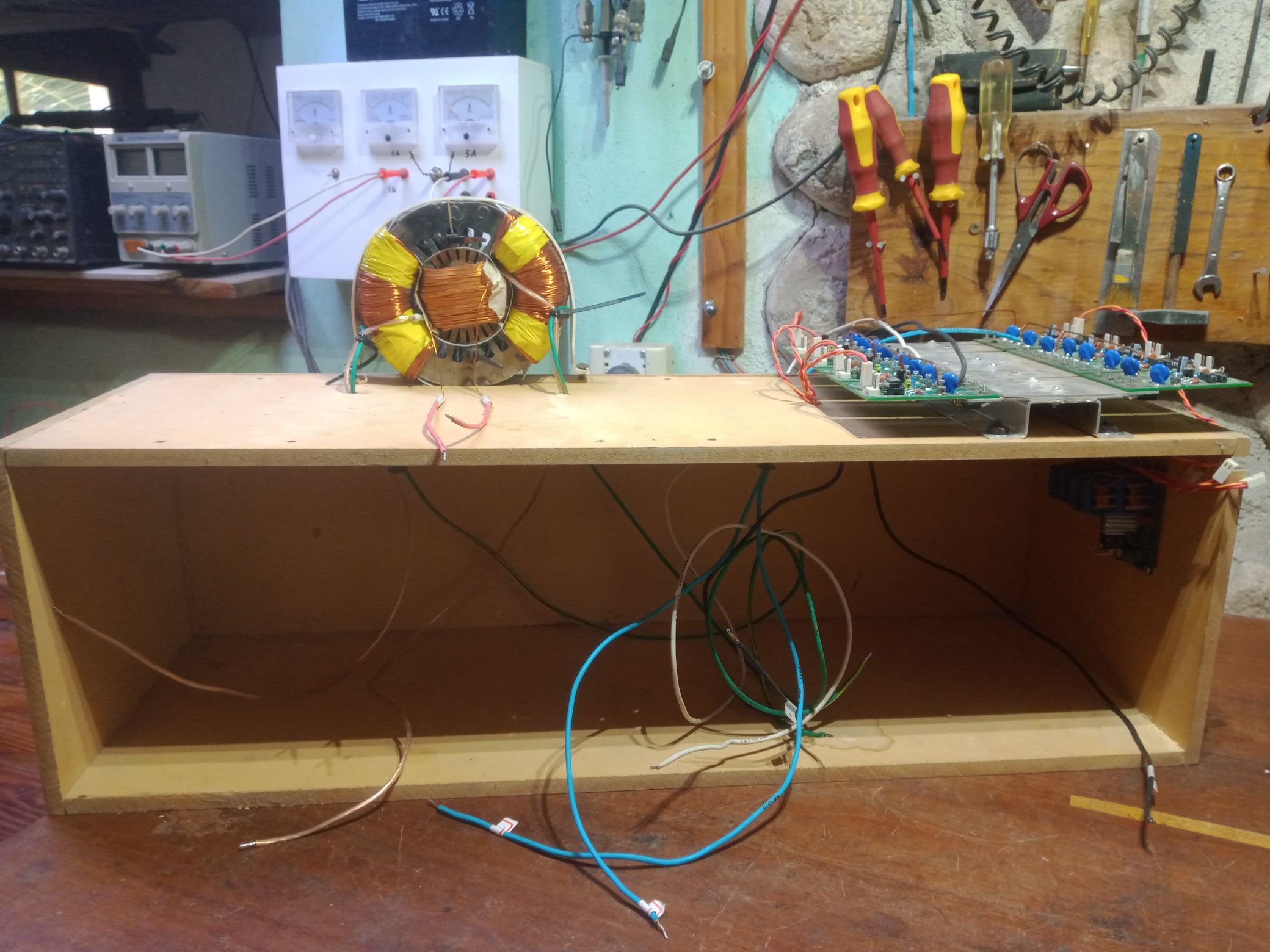
From a remainder of one of these setups I build this coil arrangement:

I do not think that it is exactly the geometry used by Figueras, but it should reveal some data about the magnetic paths and the dynamic impedance of the exciter array.

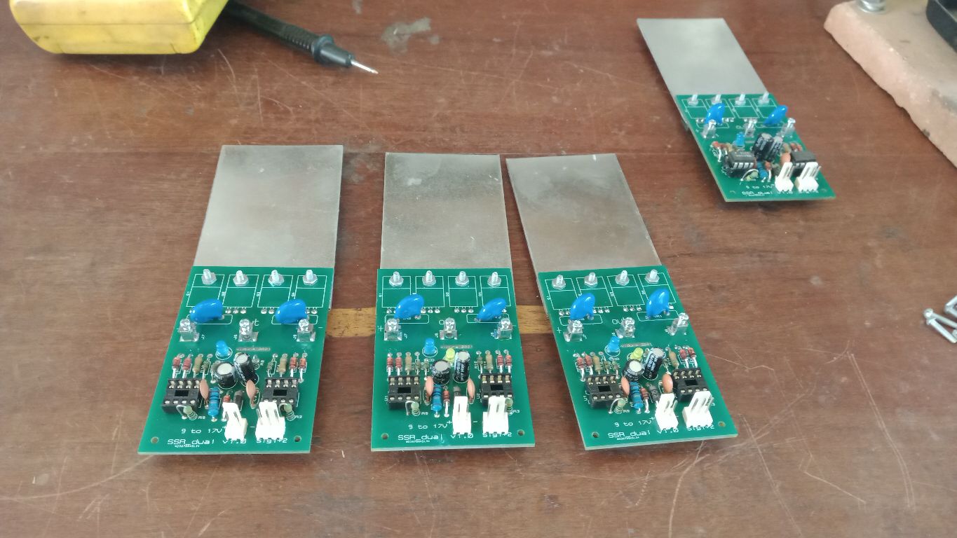
Also, the SSrelays used in the DZ project will be reused. A multichannel driver power supply was built, which provides a transformer insulated output for each relay. The signal will be provided by an Arduino board, which will it make easier to replicate for others.


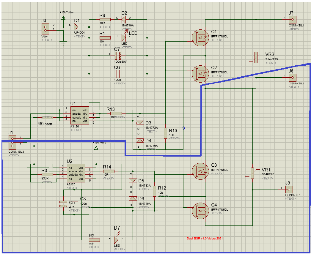
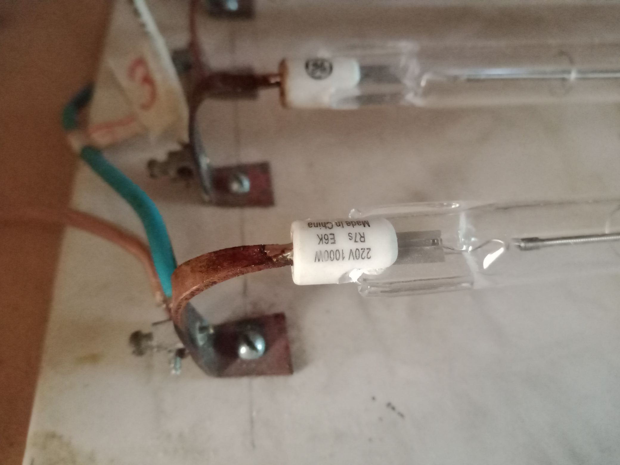
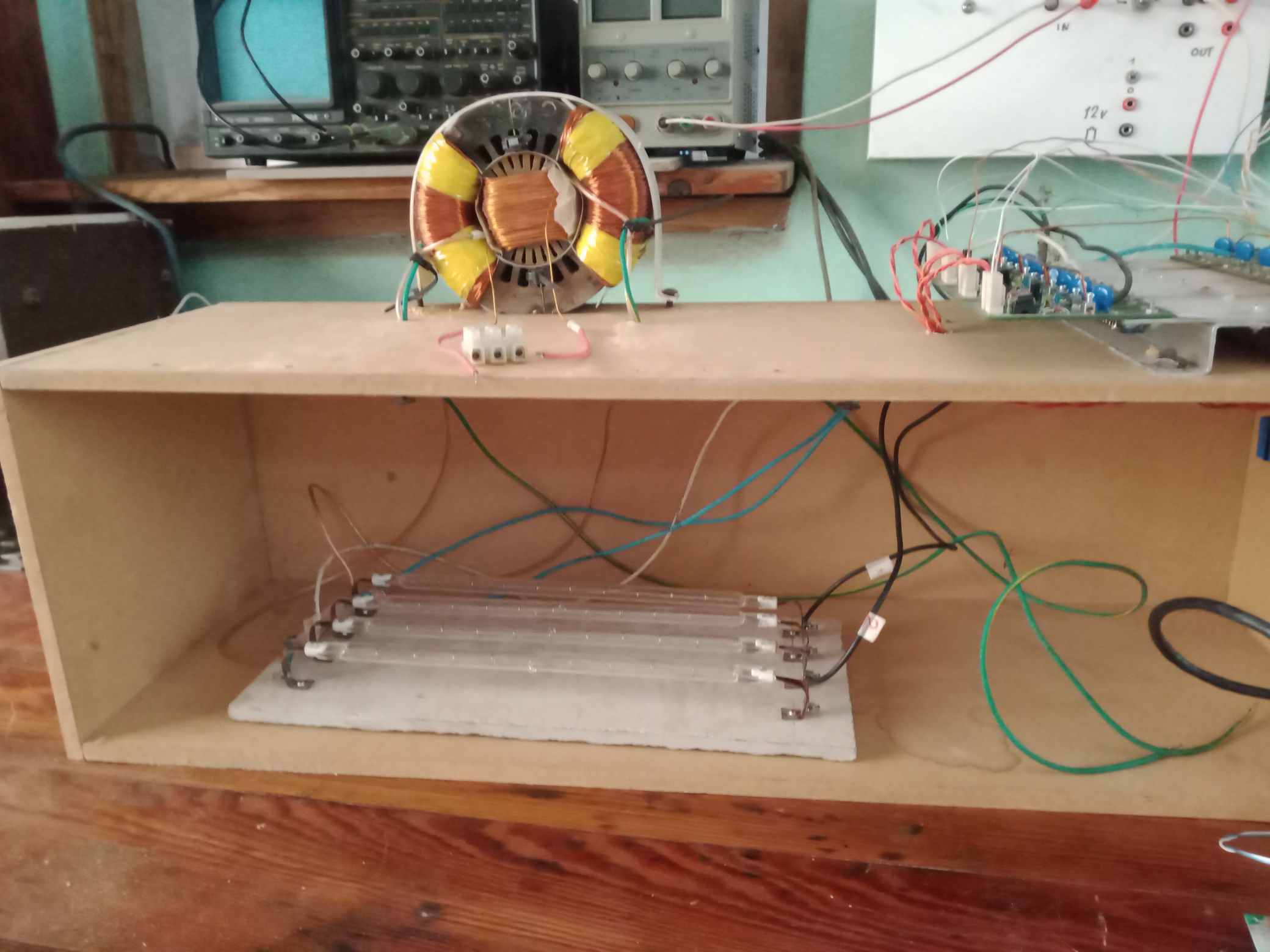
I will use only the low side part of the dual SSrelay modules which is marked inside the blue line. For the resistor array I will give a try to use some 1000w incandescent halogen tubes, although I’m not at all convinced with this solution, maybe I will go back to the custom-made wire wound resistors.


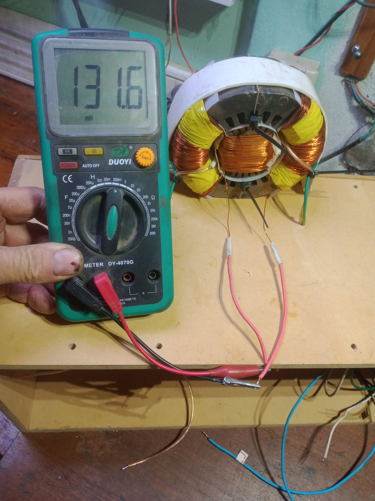
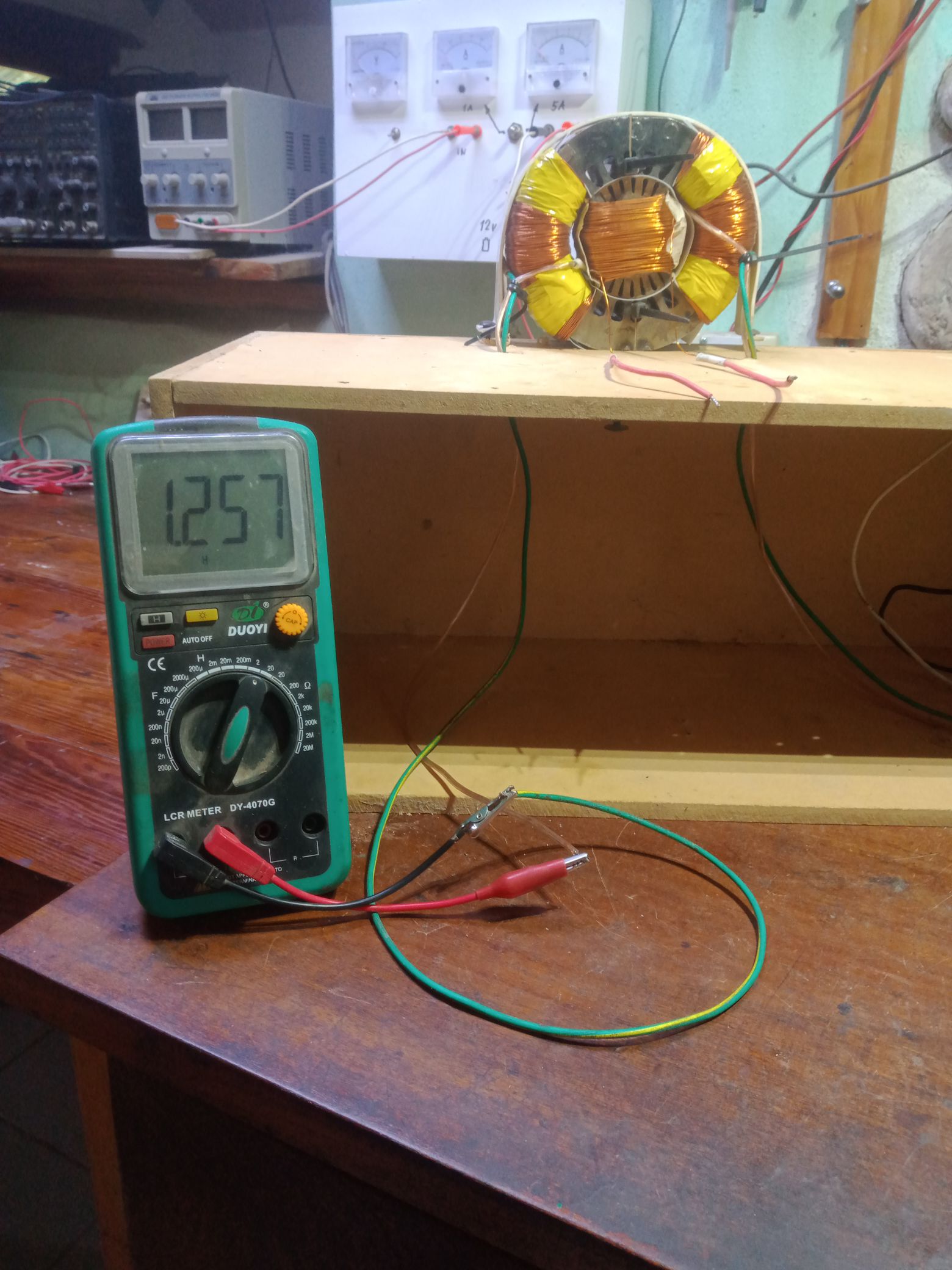
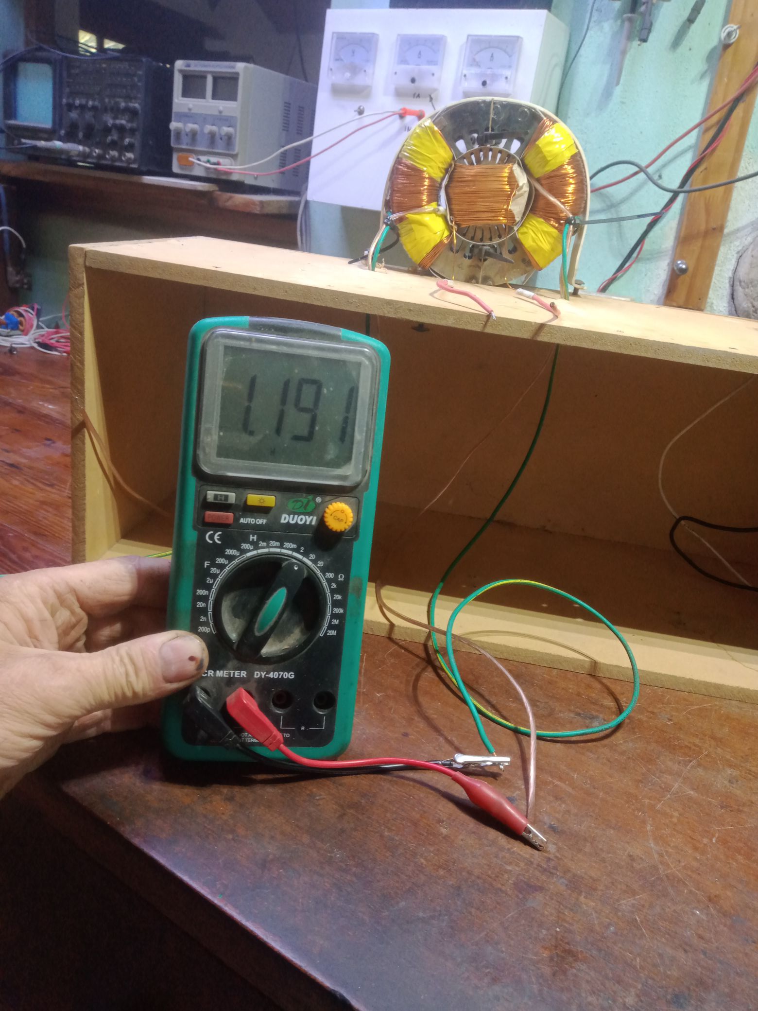
Some more images with some measurement. I will follow Fighters example of documenting as accurate as possible. The inductance of the exciter coils is important for the rise and fall time of the current. The Dc resistance is 16 ohms.

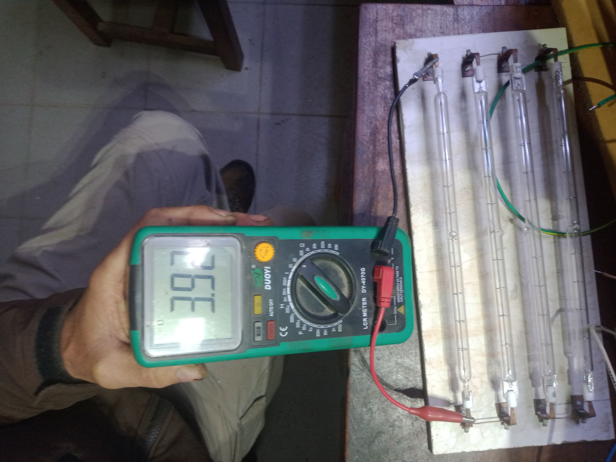
Below the incandescent halogen bulbs, at working temperature they should have 48.4 ohms, but the cold filament has only 4 ohms. It should settle somewhere in-between in the experiment. Also, an adequate voltage for the exciters will be tested.  

Starting to prepare the first experiment, only five channels will be used. Below the SSrelays in the wooden box you can see the driver power supply.


Vidura

Vidura posted this 21 April 2024

Some steps closer to finish the experimental setup. When i connected the 1000w halogen bulbs I realized that the contact with my custom made socket was faulty. As I sow in baerndorfers video the bulbs can be soldered with tin, so I fixed the issue this way.


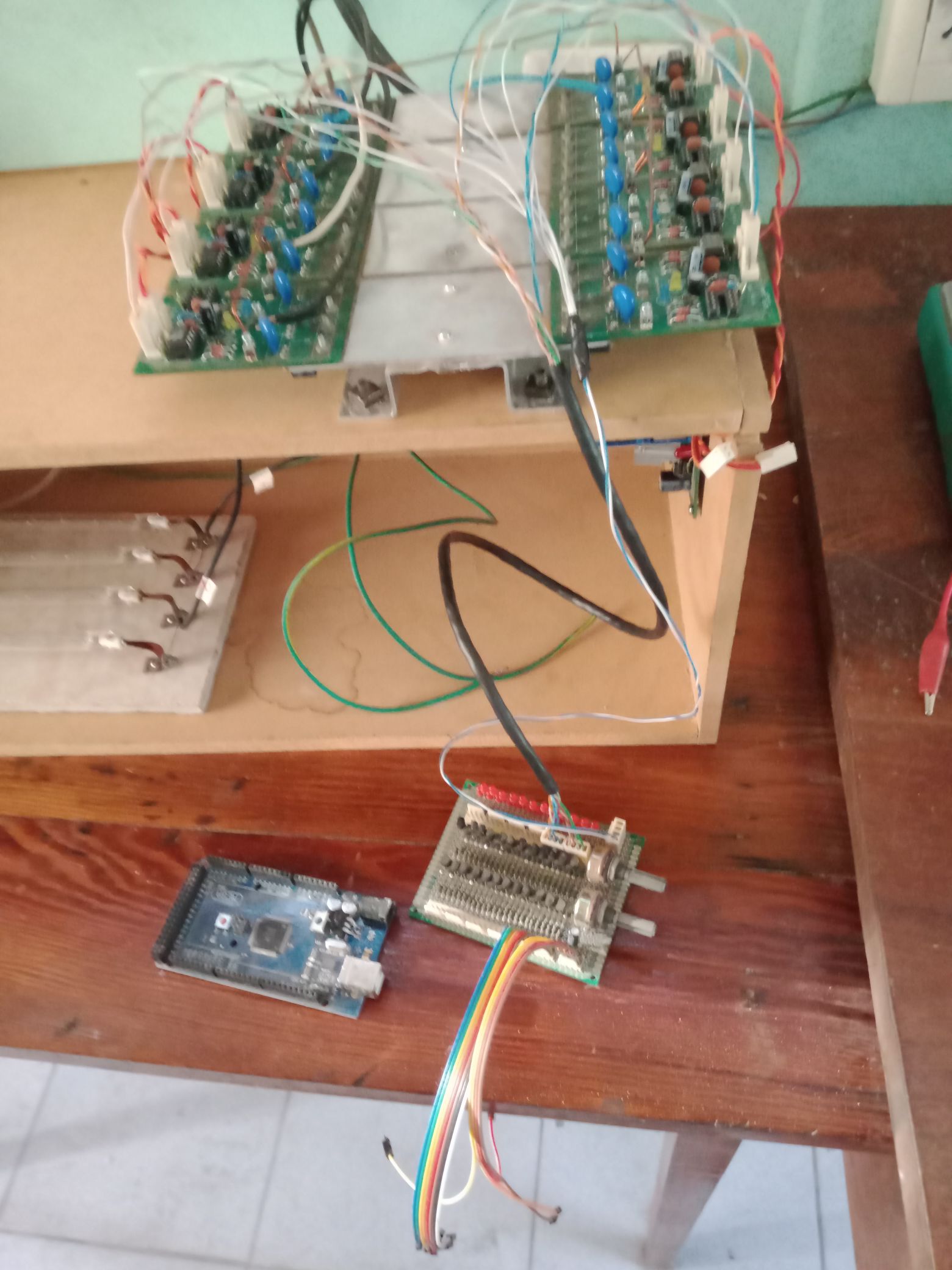
In the image below the interface for the Arduino and the connectors for the SSrelays:

Still i have to assamble the supply connections for the arduino and the driversuppy, some more wires and program the Arduino for a serie of tests. First I will run it from a 12 volt battery , the low cold resistance of the bulbs might be an advantage for this. Only 5 channels will be used for the four resistor array, althought the setup is prepared for 8 channels.

Vidura

Atti posted this 21 April 2024

Hi Vidura.


it is a bit difficult for me to understand and translate videos and I didn’t know about the question circle on tour YT channel. Therefore, I apologize if I missed something. I will only ask you one question: Could you from your experiments get some conclusion if another magnetic field exists, which is not the magnetic vector?

If you haven't seen it yet. You can read more about the questions on the YouTube channel and the experiments I performed here.   https://www.beyondunity.org/thread/is-an-automatic-system-possible/


Well, first of all, we have made a mistake of interpretation and more than likely a mistake of translation.Please bear with me.
 But what I wanted to refer to.

It is known from the operation of the synchronous generator.

The maximum voltage is associated with the minimum magnetic field strength, the maximum voltage is associated with the maximum magnetic field strength, contrary to what one usually thinks.Because the maximum voltage is induced at the maximum flux change and not at the maximum magnetic field strength. 
If the excitation occurs in good phase, it is just the same excitation current as in a synchronous generator in general. The only difference is that the rotor does not appear to rotate, and in fact, without excitation, it does not 
it does not even come together as a single rotor.

Since the energy of the precession iron atom is derived from the kinetic energy of the electron, we end up subtracting some of the kinetic energy of the electrons, depending on the success of the technical solution.
It is even more complicated in practice.

It's not enough to get the frequency right, you have to know the phase angle, you have to know the cone angle.In other words, you have to arrange everything in space so that the force of the excitation has no effect on anything. So don't introduce unnecessary energy into the system.
This system wants to take energy from everywhere.If it can, it will take energy primarily from excitation, but if not, it will take energy from other possibilities. Permanent magnet, static field, etc.But this is different from the Figurea generator.


Thank you, Atti.

Vidura posted this 22 April 2024

Thank you for the comment, Atti. I agree with what you stated, as far as we hold on the atomic model from Bohr. (Tiny spheres spinning around each other). We know that in the generator the biggest part of input energy is used to overcome the magnetic interaction between the spinning exciter magnet and the output core as mechanical force to keep the rotor spinning. The approaching pole is repelled and the leaving pole is attracted by the output core when current is drawn from the load. In the Figueras generator the same thing happens, but the difference is that the attracting or repelling force will not affect, as the exciters are fixed. Of course in this scenario the variation of the two electromagnets resembles the spinning magnet, and some amount of energy has to be used to produce the variation. The key for reaching COP>1 is how to deal with this magnetic fluctuation produced by the load current. Is there a possibility to attenuate the Lenz' reaction? If a significant part of it can be captured and dissipated, the COP>1 should be achievable. My idea is that one of the two reciprocating exciter coils can capture the magnetic force of the output core and dissipate in the resistor array. The scope of the experiment is to test this concept.

Vidura

Vidura posted this 28 April 2024

Hi All.

Today I found some time to run a first test of the setup, here I will share the video.


Vidura

Vidura posted this 29 April 2024

Here test number 2:

The halogen lamp array has been replaced by the self-made 27-ohm resistors. The other parameters are identical. Here the video:

The current oscillations have increased a little, but are still far too small. They oscillate between 100 and 200mA now, although the output has increased to twice the value than in the previous test, it becomes clear that the resistor values have to be much greater. The resistors became warmer than the lightbulbs in the previous test. To perform the next test, I will assemble a new resistor array and also add three more channels, which will increase the total resistance further. 

Vidura

Close