This thread is a copy from the proboard forum. As the topic is important for understanding the principals of propagation of electric energy I decided to publish again in the new site. Eventually some details will be corrected by the way.
This thread will be dedicated to longitudinal waves and the related phenomenon's of physics. As an introduction I would like to remind you that the human brain has two hemispheres, each one dedicated to a specific kind of processing information. Nowadays the term knowledge is uniformly associated with the accumulation of information, and it's processing with a kind of binary logic. This capabilities are mostly located in the left hemisphere of the brain, in contrast the capacity to understand by the way of analogies , images and intuition are domains of the right hemisphere of the brain. There is certainly a insane unbalance of this capabilities in the present time, as from early stages of the educational system there is paid attention almost exclusive to the "left hemisphere intelligence", while the other side is left to its own, without any training in most cases. In order to develop the whole potential of our intelligence-knowledge, it is necessary to train both sides of our brain with their associated capabilities, as they are a conjugate pair. This will require some practice and time, but finally it will enable us to gain an integral understanding of the phenomenon's of the physical world and beyond, and transcend the limited "binary logic way of thinking" . This is the reason why we will use analogies of the properties of sound-waves in this topic, as it will help us to get a better visual and intuitive understanding of the electrodynamic equivalents.
First we will have a look at the properties of a sound-wave inside a tube, and analyse the processes in detail.
We will be discussing only the simplest form of waves (called linear waves). Most sound waves behave as linear waves since they produce pressure fluctuations in air that are very small compared to the atmospheric pressure. This will be sufficient for the beginning, as it represents quite good the basic behaviour of our analogy, which will be an electric conductor(long line).
Waves transfer energy without transferring matter.
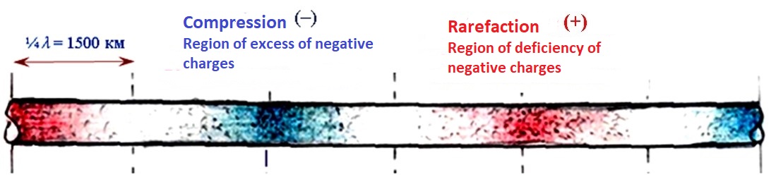
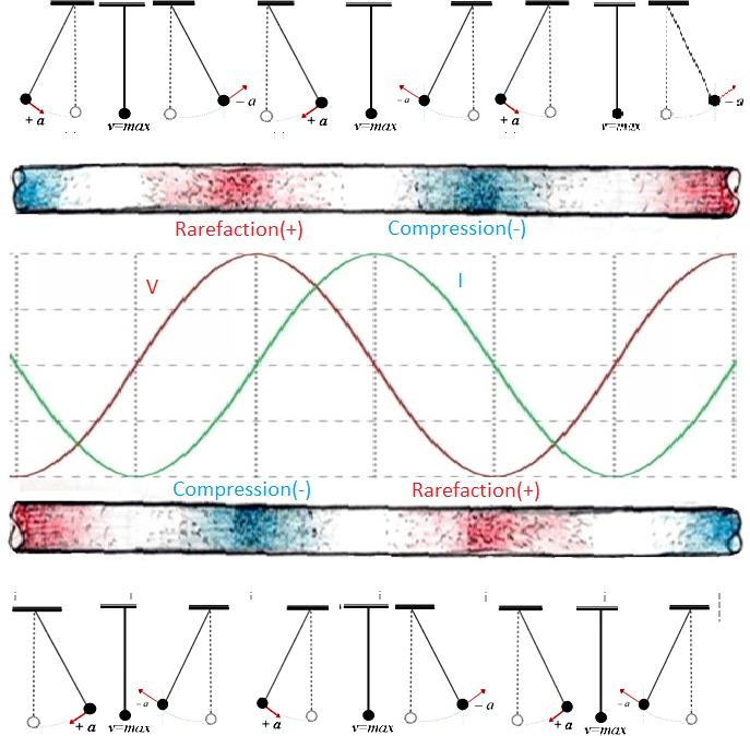
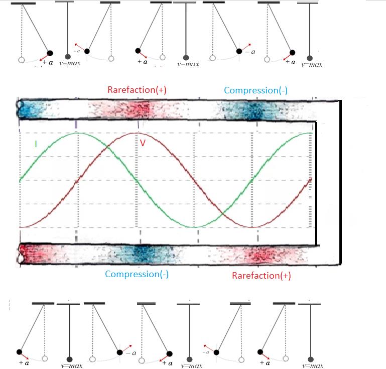
Let us consider air particles set in motion by a vibrating piston. We can see that the particles (the black dots in the animation below; three of these have been coloured red for illustrative purposes) move back and forth about their equilibrium position, thus creating alternating zones of compression and rarefaction. In the rarefied region, the pressure is less than the normal undisturbed atmospheric pressure, denoted Patm, and in the compressed region, the pressure is greater than the normal undisturbed atmospheric pressure, as shown in the animation below.
As you can see, it is the disturbance which travels, not the individual particles (if in doubt fix your eye on one of the red particles). In sound waves, also known as acoustic waves, the local oscillations always move in the same direction as the wave. Waves like this are called longitudinal waves.
The velocity of a wave in a given medium (air, water, etc) is fixed and is related to the physical characteristics (temperature, density, etc.) of the medium.
But the frequency and thus the wavelength and the amplitude of the difference of pressure are dependent on the source, in our example from the movement of the piston.
For greater clarity, I selected key frames from this animation, which captured the individual stages of the red piston movement and the resulting deformation of the elastic air. Let's analyze them.
Below in the image, the piston (sound source) is on the left (at the bottom dead center) and starts moving to the right with some acceleration.
.jpg)
When the piston moves to the right, air molecules condense in front of the piston, increasing the pressure in front of it (despite the tendency of the molecules to scatter in different directions).
.jpg)
In the upper image the piston continues its movement, forming condensations of molecules in front of it.
In the middle frame the piston continues to move, but already with maximum speed, and the wave of compression of molecules (but not the molecules themselves) in front of the piston continues to grow.
In the lower frame the piston stopped at the top dead center, forming a maximum concentration of molecules in front of it, after which the longitudinal wave, under the action of inertia, continues to move independently along the air channel at a constant speed.
Vidura
.jpg)