
I transferred my thread on Ferrite at Work here to BeyondUnity.org
What we consider to be empty space is merely a manifestation of unawakened matter. N.T.
I transferred my thread on Ferrite at Work here to BeyondUnity.org
What we consider to be empty space is merely a manifestation of unawakened matter. N.T.
ello everyone .. We replicated this circuit but still without success .. after switching on the voltage on the battery increased but only for about an hour, then everything turned and discharged .. we had it built on a cup core .. today we ordered a toroidal ferrites .. so I'll see when he arrives and remake the whole device from the beginning ... I didn't even have curves on the oscilloscope like Jagau had. Either it all vibrated and the diodes lit up differently but there was a large current consumption from the battery or it pulsed with flashing LEDs but the battery was still discharged .. the only thing we observed was that the frequency of LED flashing increased ..
How nice will the ferrites arrive, I will add further information, including photo documentation ... What is your experience of others with this connection ...?
Hello friends
Back from yet another week of travel.
Still a lot of material to read, I will give you some good news soon.
P.S. hi strape round ferrites are absolutely necessary, keep us informed of your results when you have received your ferrites.
Jagau
What we consider to be empty space is merely a manifestation of unawakened matter. N.T.
Hi all experimenters
The next step in this wonderful little circuit is to find out what its consumption is in Watts and you have to bear in mind that this measurement is taken after more than 4 weeks of operation.
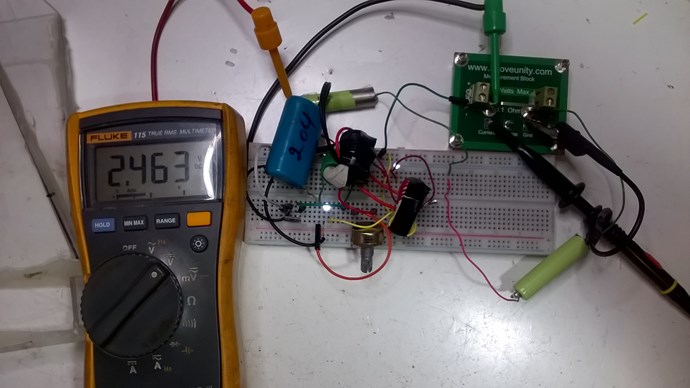
Using my DDM we can read a consumption of 4 milliampere or 0.004 A. and this on 2 batteries of 1.2 volts, which gives us a total consumption of 0.004 X 2.463V = 0.009852 watt or 9.852 milliwatts.
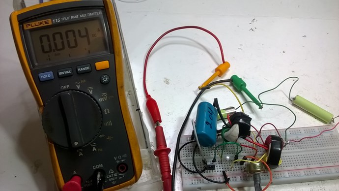
with 2.463 volts
As the precision with a DDM is not as precise as with the oscilloscope here is a measurement taken with my oscilloscope.
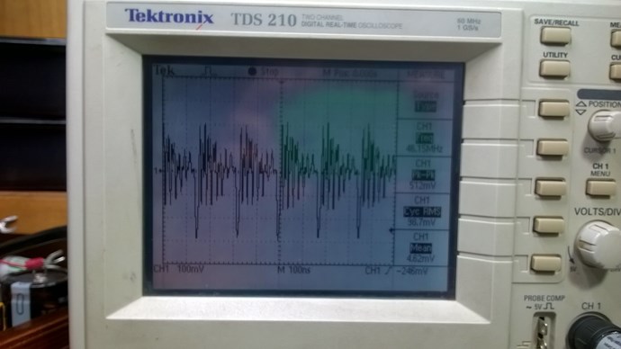
taken through a precision resistance of 0.1ohm see mean voltage, we can see that the measurement is even more precise, 4.62 milliampere.

So now we have 4.62ma X 2.463v = 11.379 milliwatt
When you calculate how long with this type of circuit the two 1.2 volt batteries would discharge
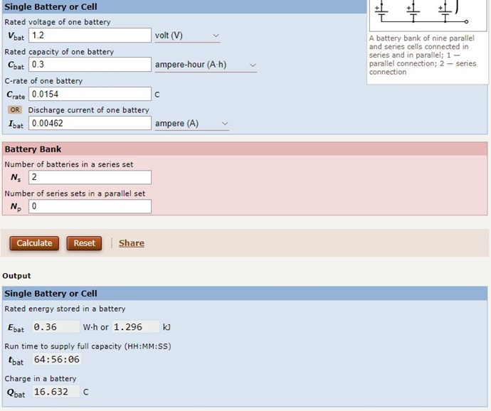
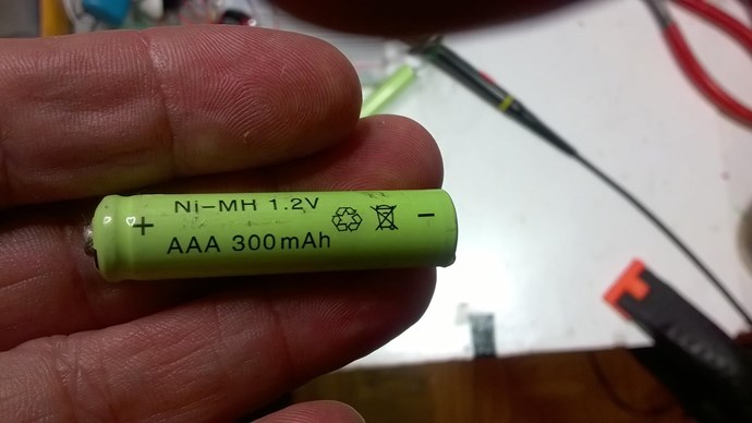
Battery used 300ma 1.2 v X 2
you can see that after runtime of 64.56 hours or near 3 days later the batteries would be dead.

And this circuit is still working after more than 30 days and no sign of weakness.
A further study of this circuit is therefore required, slowly but surely by taking a lot of notes and photos as Chris advises.
The next step will be to find out what is the maximum power it can consume without draining the batteries.
Jagau
What we consider to be empty space is merely a manifestation of unawakened matter. N.T.
Hell all
A fifth week without failure.
Tell me Mimo is it still working for you?
I think there is also KalleFin who had good results, keep me informed of your results.
Jagau
What we consider to be empty space is merely a manifestation of unawakened matter. N.T.
@Jagau, and the team
30th day for the one with the Litz wire : 2,07 volts, in fast flashing mode. Slow decline, but 30 days anyway.
The other copper wire device is very weak, but still on in fixed mode. I did not measure it. The best luminous performance is the litz wire (same ferrite toroids).
Greetings
Mimo
Hi Mimo
Hello Mimo, I am very proud to hear you say that.
I think there is something we need to investigate for sure, thank you so much for answering I was feeling a bit lonely, but it gave a boost of energy , I think we are making the future of this thread and what is coming.
If others have good news I look forward to hearing from you.
Jagau
What we consider to be empty space is merely a manifestation of unawakened matter. N.T.
Hey jagau and all following. I'm glad that some have good results with the circuit. In my first experiment it performed well, rising the battery in a few hours, then I made some improvements, without success, and Couldn't find the same parameters again. I used two toroidal cores out from common mode chokes. Anyway I want to tell that I have not spent much time with the circuit, as I am working on a couple of other projects and don't want to disperse too much. Also my free time is limited, a lot of work to do and difficult economic situation. Maybe at a later moment l will recover to investigate this circuit. Best wishes, Peace for all. Vidura.
Vidura
Hello everyone.
I'm still failing. I already have new ferrite toroidal cores. We did everything according to the original plan at the beginning of this thread .. then we turned the winding of the L3 coil. there is always a drop in battery voltage .. we tried to measure on an oscilloscope and I can't find the same curve on the collector as my Jagau .. so what to watch out for? Yesterday I rewound the coil L3 in the same direction as the L1-L2 bifilar and turned the diode .. everything is the same, the voltage still drops. as i found out, the frequency that arises on the oscillator cannot be influenced, the potentiometer can only accelerate the number of pulses until full oscillation occurs .. I will try to make some pictures ..
Hi all
@ Vidura, your comments are always appreciated here my friend. You have done a lot for this forum with practical experiences.
@Strape
Have you tried this easier to read diagram?
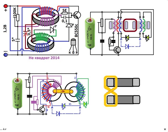
To help you try with a voltage of 2 batteries 1.2 volts at the beginning it is easier to debug.
With your images I may be able to help you better.
Jagau
What we consider to be empty space is merely a manifestation of unawakened matter. N.T.

No one online at the moment


