
I transferred my thread on Ferrite at Work here to BeyondUnity.org
What we consider to be empty space is merely a manifestation of unawakened matter. N.T.
I transferred my thread on Ferrite at Work here to BeyondUnity.org
What we consider to be empty space is merely a manifestation of unawakened matter. N.T.
@Wistiti:
Could you share with me the layout of the charger you show a couple of posts up. I wound up the coil as per the pictoral view but it seems lacking to me. I would like to unleash this on a 12v slab removed from a UPS to see if it will have the same results as you. I have some Tip series transistors that should work great for this. Thanks much
thay
Hi thay. I'm away of home right now but when I get back I will do it with pleasure! And will check the voltage of the battery too!!
Hi Team!
After more then 2 days my 6v battery goes down to 6,048v. It is still over the 6,038v before running it at the beginning.
I will let it run to see if it continue to drop.
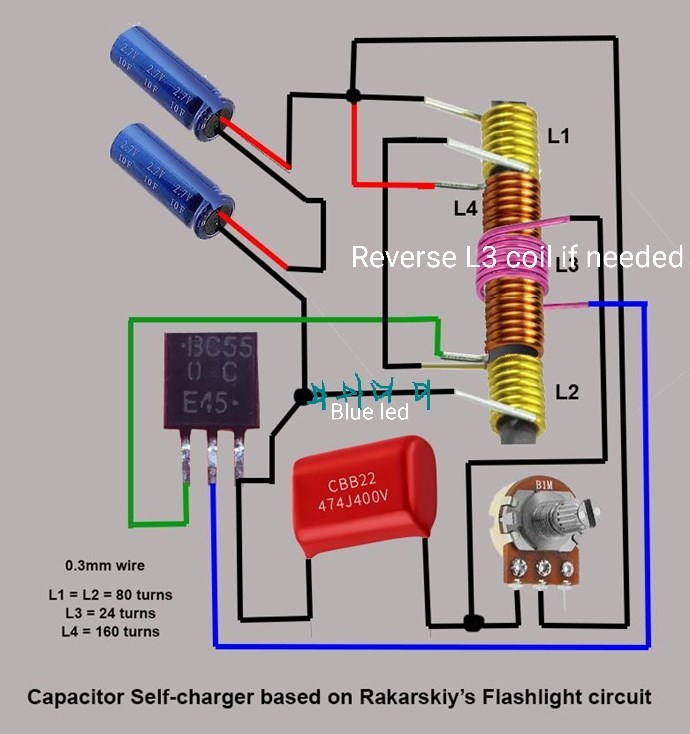
Thay here is the way i connect it.
Im curious how other experiment are going..?
Sincerlly!
Hi Wistiti, I have the same problem. with the charging circuit and the Jagau circuit. The effect is the same but the speed of changes, is depended from the capacity of battery that is used. It charging at the beginning.. after some hours/days will keep the voltage stable... and after some hours/days the voltage decrease. This reminds me the magnet/plasma circuits experiments.., this seems to happen with such circuits.
Maybe a solution would be to alter the circuit to charge another battery, and swap the two batteries to keep going. At the form of split positive for example. When I get some free time I will try to do that..
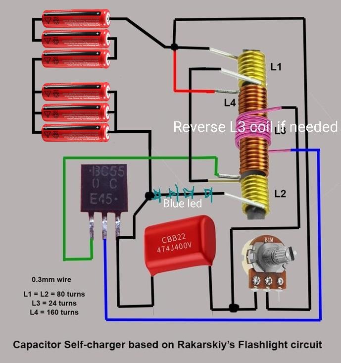
I’m not saying I did everything right. It's just a simple one
I'm a replicator.
Unfortunately, I still can’t report good results. Over time, the batteries slowly discharge. NiCd NiMh and lithium. I took a picture of the shape of the charging current. The preparation was based on the given parameters.I also tried several layouts.
The LED flashes as told but the camera image is a delay.
I wonder what the shape of the charging current is for others.
Atti.
Rakarskiy (user name added by Fighter):
About working in long-term mode. Try connecting a load to the battery for a short time to discharge it a little. This will change its internal resistance, which should cause an increase in the charging current. (in simple terms, what you have collected, take it to the side). If the system restores the charge again, this will be the algorithm of the self-propelled device. And without battery operation, the system is balanced, so it is discharged and it is looking for its optimal balance point. Respectfully, my thoughts.
Hi everyone.
I have already done several tests of the circuit.
The operation itself is a saturation auto-oscillator
core, the series resistor that biases the base of the transistor
as is logical it will apply a current in it which in turn
multiplied by the beta will create the collector current.
It is because of this that it will be necessary to adjust said resistor so
saturates it.
The capacitor on the other hand, the main function will be that said
transistor work on common emitter.
As the feedback is positive it will oscillate
at a frequency that will be dictated by the core material,
turns, load, collector current, etc.
If you want a more in-depth explanation, let me know.
This is just an approximation, just that.
On the other hand the apparent battery charge will stop
when its dielectric absorption enters equilibrium
with the energy possessed by the peaks generated by the leakage inductance.
The best way without fear of doubt to affirm that the circuit charges
the battery would be the circuit in this image.
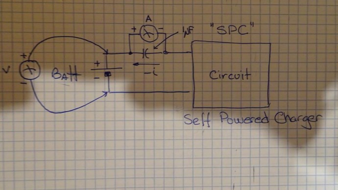
Thanks in advance.
YoElMiCrO.
Hello experimenter friends, back from a long trip. I will read with interest your experiences, a lot of late reading for me,
A small update that will interest many, the starting circuit is still in operation and therefore after more than 21 days, it works perfectly, the voltage is still maintained at 2.5 volts and does not drop.
I would like to know if if mimo and kallefin also have good results too?
Well done Atti and
Thank yoeimicro for your comments
What we consider to be empty space is merely a manifestation of unawakened matter. N.T.
@Jagau,
current results:
16th day for my first device with litz wire: 2.246 V.
14th day for my second device with stranded wire: 2.268 V.
However, I had a gradual dimming leaving the light visually fixed. To get stability, I was forced to switch to fast blinking mode.
You get a great result that I would love to reproduce. What are the dimensions of your ferrites (if it's already published, I may have missed it)?
Greetings
Mimo
Hi Mimo
Already the sixteenth day for you it's excellent thank you for the feedback Mimo.
My ferrites are Ferroxcuce 3E25 I put the pdf attached, they are the ones you see at the beginning of the thread with a small black tape on top to better hold the cables tight.
We continue it is going very well and I believe that the configuration of the beginning of the thread is the best proof is there.
Jagau
What we consider to be empty space is merely a manifestation of unawakened matter. N.T.

No one online at the moment


