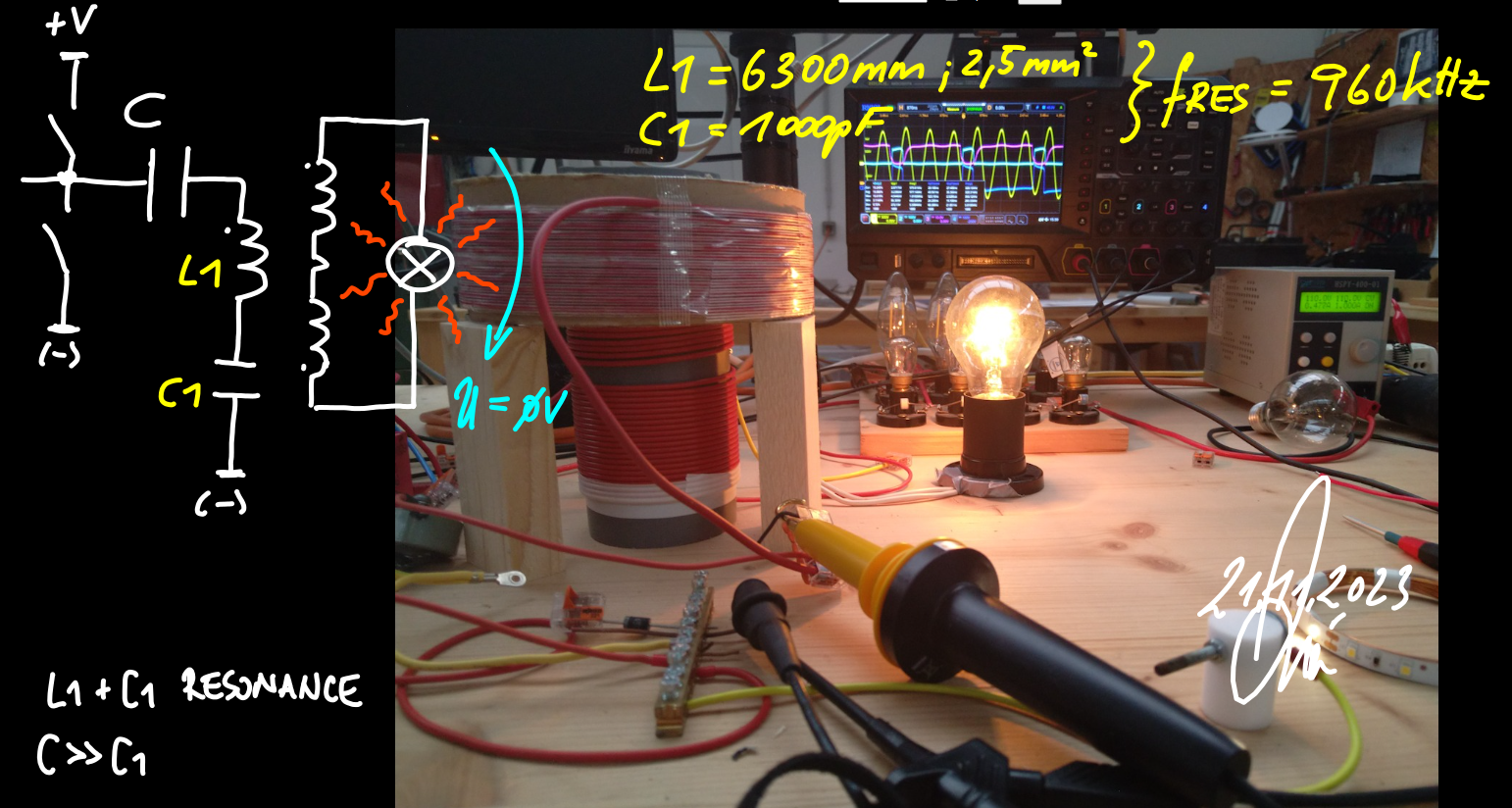
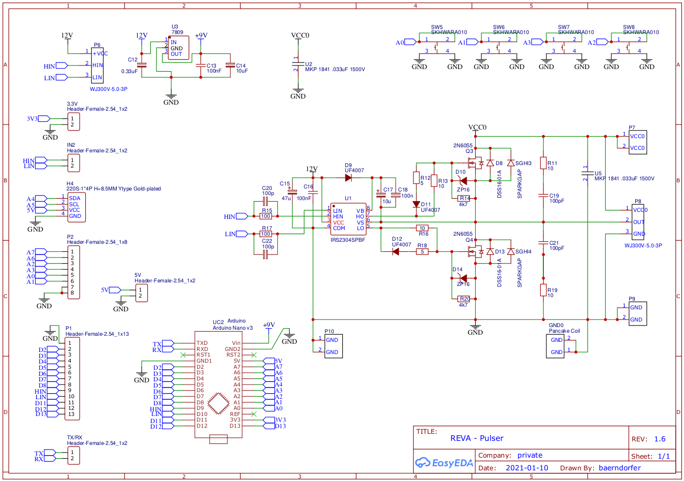
some time ago i build a halfbridge for doing experiments. the circuit looks like this,,,
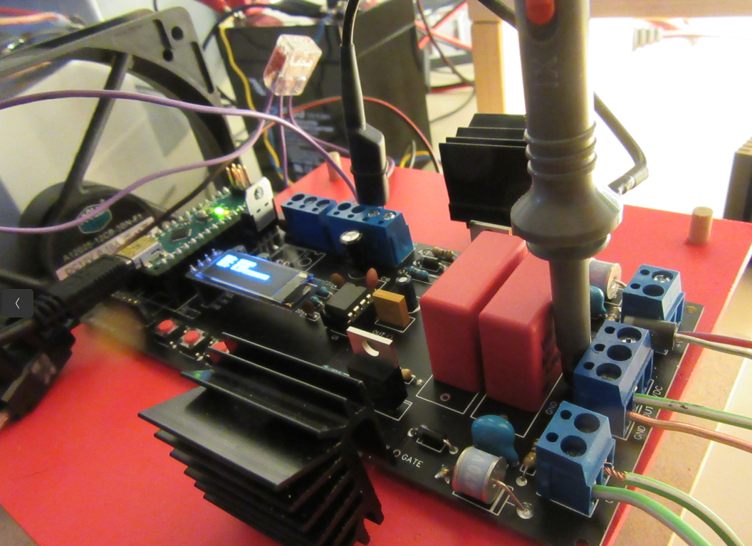
i managed to design a scetch for arduino where i can adjust frequency and duty-cycle. the thing looks like this...
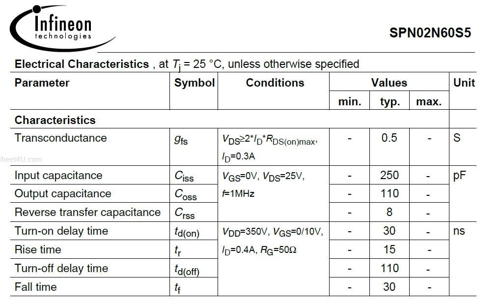
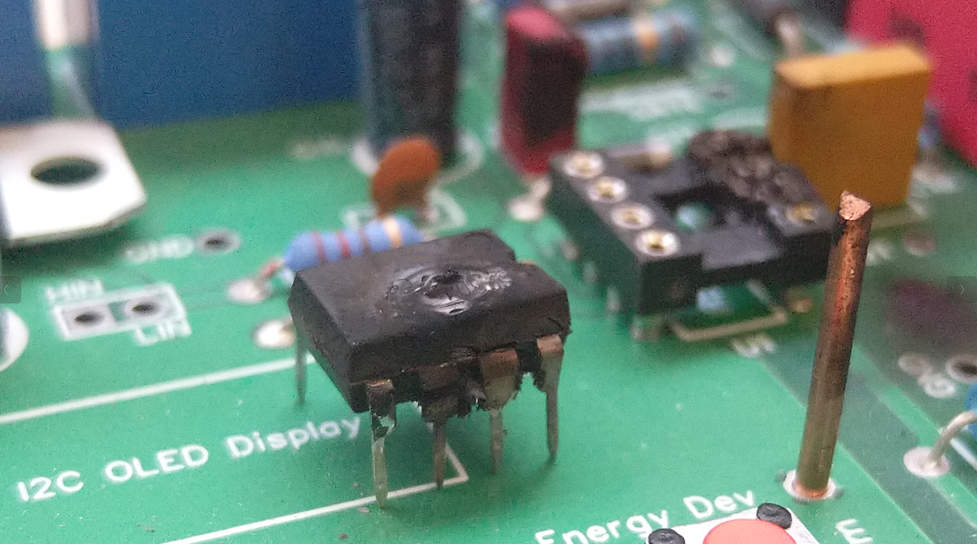
i use infineon IRS2304 as gate-driver IC.
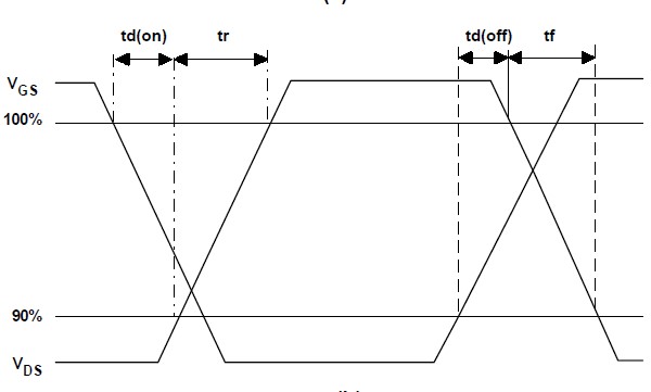
when i look into datasheet i can find information about amount of time which is taken by IC to switch ON or OFF.
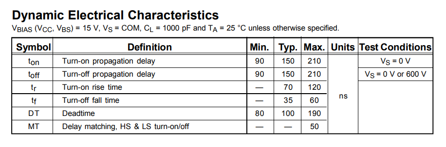
so it took between 70 and 120ns for IC to turn ON
and it took between 35 and 60ns to turn OFF
---
today i did some experiments where i use this halfbridge and on oscilloscope screen you can find output from halfbridge on CH4 under load.
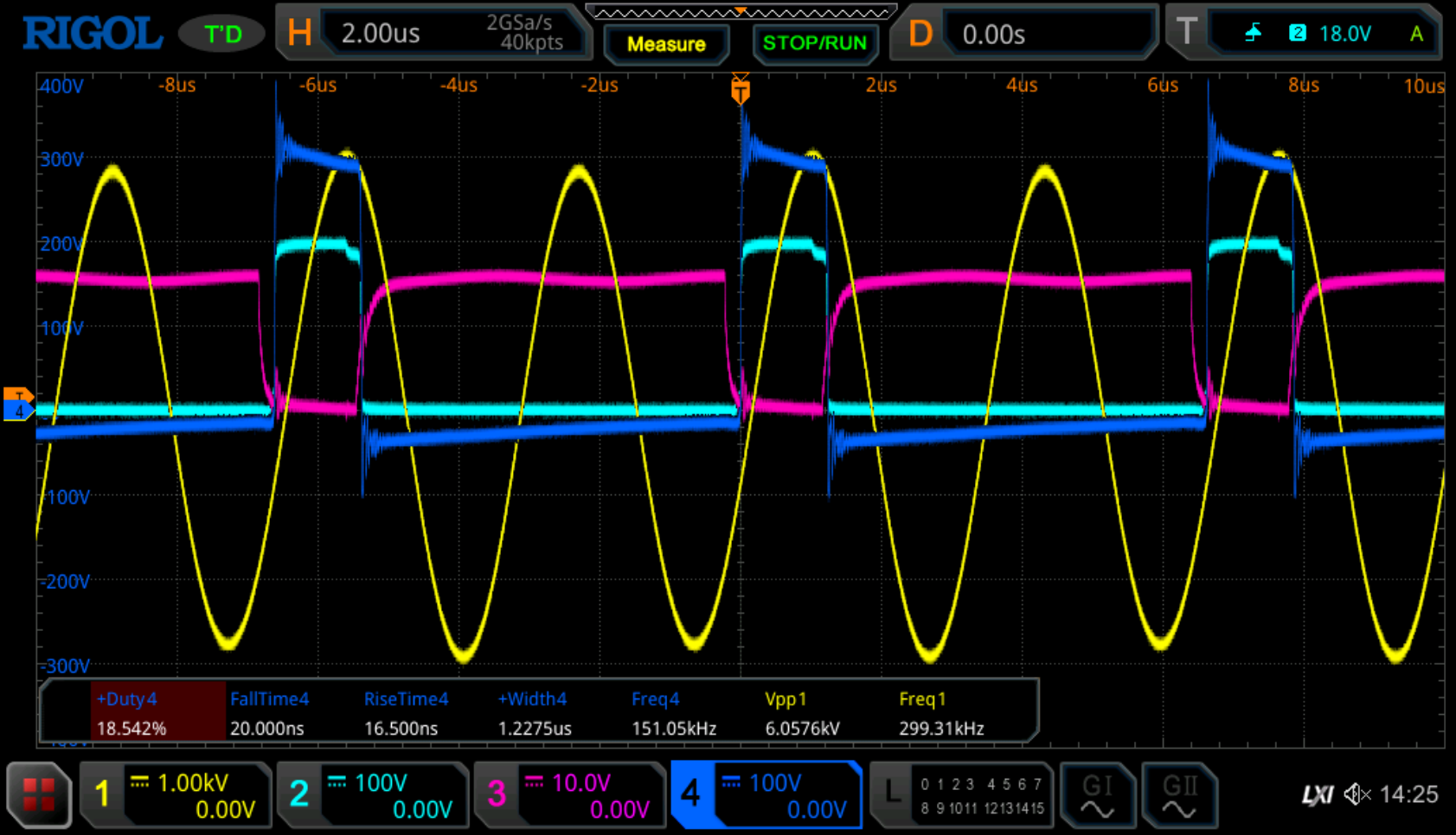
now as we can see, the RiseTime and FallTime of the output from halfbridge is incredibly fast compared to the data given by datasheet for gate-driver.
on CH2 we can see the Gate-Signal from highside-FET and CH3 represents Gate-signal from lowside-FET.
CH1 is Resonance-Signal from secondary coil-system which should be not relevant for the input situation.
at the moment i cannot understand, why the output signal has such sharp edges.
hopy some electronic-experts can help me understand better.
regards
B