Hi everyone.
I thought of the tertiary coil. I would like to mention some thoughts from my work. You will find it confusing. But then ignore it.
Here, I would like to highlight some basic ideas of large transformers. They are usually displayed on the website of the electricity supplier. So at a voltage level of 20-120-400 or 750KV. We can find a lot of literature on it, so you wouldn't single out any of them in particular.
- The switching group of three-phase transformers at different levels. The switching group of transformers determines the configuration of the primary and secondary side windings, and
indicates their position relative to each other. The phase windings of a polyphase transformer are the transformer
inside, they can be connected according to different configurations, depending on what characteristics we expect from the
from a transformer. Different coil combinations also result in different phase angle differences, which
it also limits the range of transformers that can be selected to connect the two systems.
Consider the parallel connection of transformers here.
The coil design of the transformer is designed in three main directions. Delta winding, star connection or zigzag winding.
-The way a three-phase transformer reacts to harmonics depends on the connection configuration used. In a star-star configuration, any imbalance in the phase currents results in the star point being electrically displaced and the phase-neutral voltage being unequal.
Triple-N harmonic currents appear as harmonic voltages in both the primary and secondary.
-If the primary is equipped with a four-wire system, i.e. the star point is connected to the neutral, the voltage distortion is eliminated, but harmonic current flows in the primary neutral, so the distortion is transferred to the supply system.
This can be solved by using a delta tertiary winding of about 30% of the transformer rating, which supplies the oscillating, unbalanced and triple-N harmonics, thereby preventing them from being fed back into the supply system.
In a delta-star configuration, unbalance triple N currents circulate in the primary delta winding and do not propagate to the supply system. This configuration is the most commonly used configuration for distribution transformers.
Note that all other harmonics will be fed back to the power supply and may spread widely as a result. As you might expect, the lower harmonics are the most disturbing because they are larger, less damped by the system impedance, and more difficult to remove at the source.
(in my opinion, this is a critical point in our case. But at least we cannot ignore it. It can be seen in several layouts. And we are looking for the phenomenon that one transformer feeds the other, and then vice versa. So here I am thinking of self-supply. That is, when the secondary winding changes to primary.)
-Three-winding transformer.
In some cases, in addition to the usual two windings, a third one is built into the transformers, this one
coil is called a tertiary coil, and the construction is called a three-winding transformer, which is numerous
has an advantage. The tertiary winding reduces the effect of the asymmetry of the three-phase load, rearranges the short circuit
path of currents, and is able to limit single-phase earth fault currents.
-Let's give some thoughts to the study of zigzag winding arrangement. Simply put. It is used because in case of asymmetrical loading of the three-phase transformer, the voltage in the adjacent column increases. Increased voltage can cause various problems in the network. But only in the service provider's network!
- It is still worth studying auto transformers. Mainly the current directions.
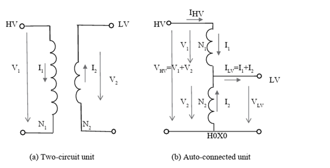
So it can be seen that this is a harmful phenomenon from the point of view of the network service provider. But from our point of view, this is exactly what we are looking for, so that the performance is returned to the source.
So it can be seen that this is a harmful phenomenon from the point of view of the network service provider. But from our point of view, this is exactly what we are looking for, so that the performance is returned to the source.
Atti.