Square Wave Oscillator Off-Grid

  • 644 Views
  • Last Post 01 August 2023
Jagau posted this 13 August 2020

Hi all
I would like to share with you this little square wave oscillator which works the same as a function generator and which operated on battery which can vary from 6, 9 or 12 volts DC according to your needs.


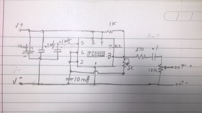
The heart of the oscillator is a TLC555 from the CMOS series which has very low power consumption and is completely different from the old NE555.

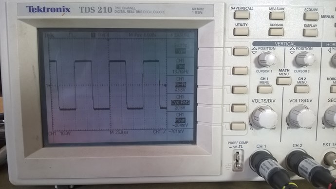
It has a 10K potentiometer to vary the frequency from 13Khz to 130Khz and another 5K potentiometer to increase the amplitude of the signal at will.


A drawing of the schematic that I present to you freehand

It can be easily changed by changing a single resistor and a single capacitor.

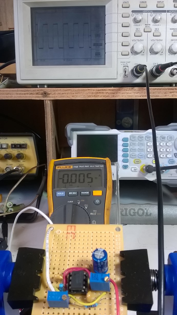
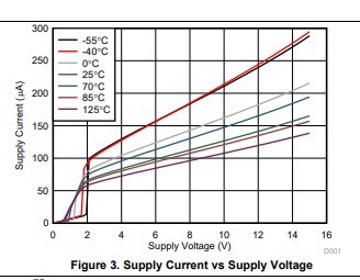
5 ma on 9 volts battery here


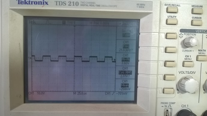
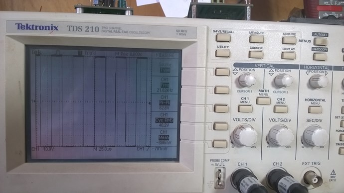
The particularity of this oscillator is that the output voltage changes from positive to negative through zero in the center. This is the AC square wave shape.

Most of these freely sold circuits are above zero volts they are only DC square wave and could not be use for experimentation.

Very low or high amplitude at your choice


This way you are isolated from the electrical network and have greater freedom of measurements without ground return.

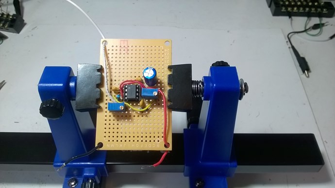
 I also hope for those who would like to join us and experiment with us and do not have a function generator, this is the ideal opportunity, easy to assemble and inexpensive.

Jagau

  • Liked by
  • AlteredUnity
  • Inception
Order By: Standard | Newest | Votes
Jagau posted this 13 August 2020

Hi all
I would like to share with you this little square wave oscillator which works the same as a function generator and which operated on battery which can vary from 6, 9 or 12 volts DC according to your needs.


The heart of the oscillator is a TLC555 from the CMOS series which has very low power consumption and is completely different from the old NE555.

It has a 10K potentiometer to vary the frequency from 13Khz to 130Khz and another 5K potentiometer to increase the amplitude of the signal at will.


A drawing of the schematic that I present to you freehand

It can be easily changed by changing a single resistor and a single capacitor.

5 ma on 9 volts battery here


The particularity of this oscillator is that the output voltage changes from positive to negative through zero in the center. This is the AC square wave shape.

Most of these freely sold circuits are above zero volts they are only DC square wave and could not be use for experimentation.

Very low or high amplitude at your choice


This way you are isolated from the electrical network and have greater freedom of measurements without ground return.

 I also hope for those who would like to join us and experiment with us and do not have a function generator, this is the ideal opportunity, easy to assemble and inexpensive.

Jagau
  • Liked by
  • AlteredUnity
  • Inception
Fighter posted this 01 August 2023

With Jagau's approval I imported this thread from the old site archive.

It took some time for importing it but the operation is now complete.

There are two reasons I did this:

  1. It's a very nice tool to have in our Hardware section, useful for low-power off-grid experiments needing true AC pulses with adjustable frequency and voltage;
  2. I intend to use it with my Don Smith Effect experiments and it's useful to have references/details about it here.

Of course in the meanwhile Jagau came with a new more advanced tool, his Arduino MOSFET Driver, but for now this oscillator is a good candidate at least for the beginning of my experiments about the Don Smith effect.

Of course all credits for this device are going to Jagau.

Thanks,

Fighter

"If you want to find the secrets of the universe, think in terms of energy, frequency and vibration."
Nikola Tesla
Jagau posted this 01 August 2023

Thank you for the import you have a patience that I do not have. thanks again

And also with the excellent advice of Yoelmicro becomes a must for your lab

Jagau

Fighter posted this 01 August 2023

Replying To: Jagau

You had the patience to design, build, test and teach us how to build this device.

Importing the thread here for our entire team is at least I can do to thank you.

There are so many threads we should have imported here. Unfortunately the process can be made only manually, it's time consuming and the available time is limited. In time we'll have more information imported here.

Fighter

"If you want to find the secrets of the universe, think in terms of energy, frequency and vibration."
Nikola Tesla
YoElMiCrO posted this 04 December 2020

Hello everyone.

@Jagau.

With that circuit you shouldn't have problems with distortions
below 500KHz, of course this, according to the mosfet driver
you use.
It can be any driver, inverter or non-inverter and 1Apico
Minimum.
Capacitors must have a minimum value, for example
4.7uF.
What you should do is put a serial potentiometer between
the output of the driver and your POT, look for the resonance frequency
and then adjust your potentiometer in such a way that I accentuated the peaks
tension that appear at the beginning of your waveform,
once this optim in frequency and impedance you calculate a
inductor in such a way that it possesses the same resistive value as the
potentiometer at working frequency.
This way you wouldn't lose coupling power between your POT
and the driver.
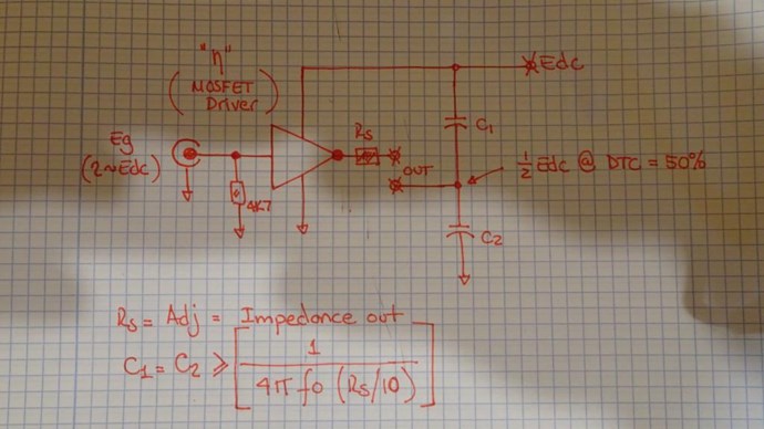
This serial inductor should have a value (Serial Potentiometer Value/(2*Pi*Fr)).
And capacitors should be greater than or equal to 1/(4*Pi*Fr* (Serial potentiometer value/10)).
Any doubt you let me know.

YoElMiCrO.

Jagau posted this 30 October 2020

Hi fighter


For the first question, the capacitor is a 0.1 uf or 100 nf


For the second, the manufacturer tells us that this integrated circuit allows you to easily make a 100 ma well with a 10 ma power supply within these limits if your leds do not exceed 100ma I do not think there is a problem.

According to this charter, you can even go up to 300ma but the IC will heat up,

Anyway, the output is fully compatible with cmos, ttl and mos, you can always increase your power.

For the 2000uf capacitor at the input, we normally use  between 1-100uf  with 0.1uf in parallel. The small capacitor is used to cut high frequencies which could degrade the use of the integrated circuit and the large capacitor for the low frequency line filtering.

I imagine you want to use it as a future power source instead of a battery?

Jagau

  • Liked by
  • AlteredUnity
  • Inception
YoElMiCrO posted this 01 December 2020

Hello everyone.

@Jagau.

If I may...
This circuit meets the requirements you need.

As you can see, once you find the necessary serial impedance
and the working frequency, you can replace the resistor with an inductor,
in this way the energy you lost in it becomes null and void!.
I hope it'll do you some good.

YoElMiCrO.

  • Liked by
  • Inception
  • Vidura
UndisclosedMember posted this 13 August 2020

Hey Jagau,

This is awesome! A very nice, cheap project for anyone to take on that needs a small oscillator!

Thank You for Sharing! This is awesome!

Best wishes, stay safe and well My Friend

  • Liked by
  • Inception
UndisclosedMember posted this 16 August 2020

Great addition to the group. Has a very tight transition time but then cmos is very fast usually. Big thanks and will add to the bench soon as can order the tl555.

  • Liked by
  • Inception
Jagau posted this 18 August 2020

Hello UndisclosedMember


Yes the CMOS TLC555 has quite surprising performance especially when looking at the manufacturer's specs:

Minimum and maximum Rise time and fall time are very fast, they approach those of manufacturers of high quality function generators. These are very important parts when making oscillators.

I will be producing an addition to this oscillator shortly
to be continued

Jagau

  • Liked by
  • Inception
UndisclosedMember posted this 20 August 2020

Hello Jagau, the TLC555 is a very good choice. If you only need it to drive high impedance output like most gate drivers then it could be made significantly more efficient (likely less than 1ma at 10kHz).

  • Liked by
  • Inception
Close