Square Wave Oscillator Off-Grid

  • 644 Views
  • Last Post 01 August 2023
Jagau posted this 13 August 2020

Hi all
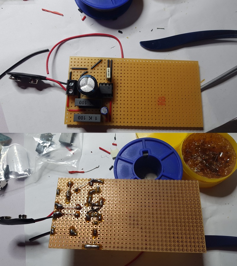
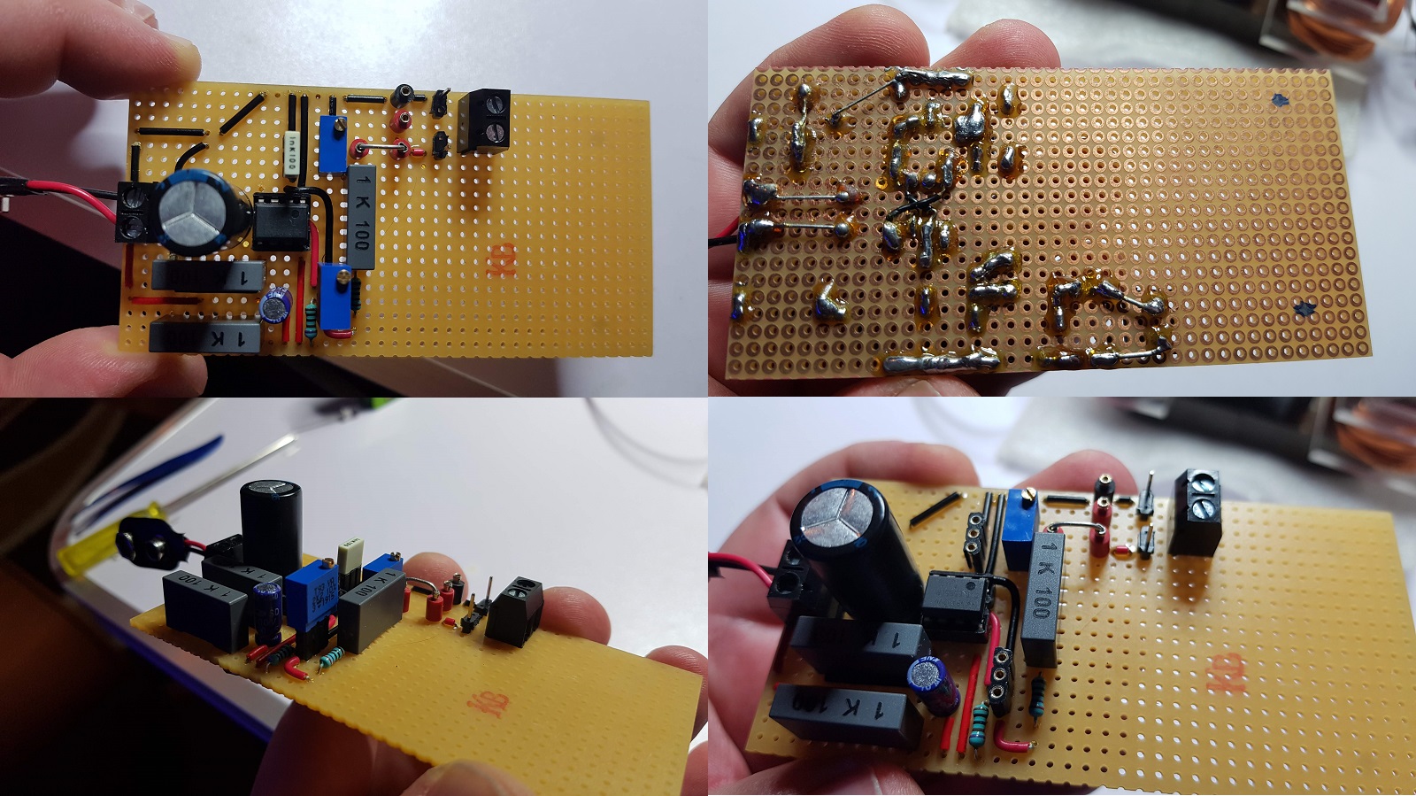
I would like to share with you this little square wave oscillator which works the same as a function generator and which operated on battery which can vary from 6, 9 or 12 volts DC according to your needs.


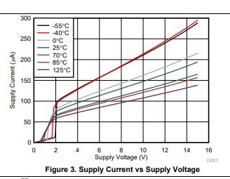
The heart of the oscillator is a TLC555 from the CMOS series which has very low power consumption and is completely different from the old NE555.

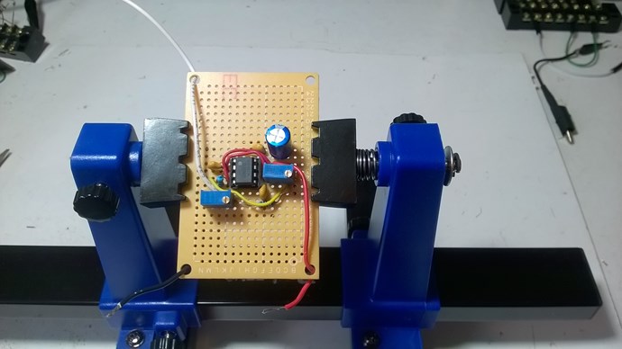
It has a 10K potentiometer to vary the frequency from 13Khz to 130Khz and another 5K potentiometer to increase the amplitude of the signal at will.


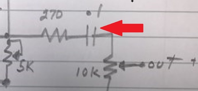
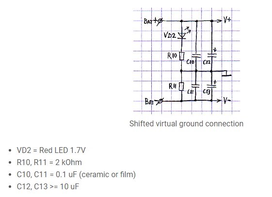
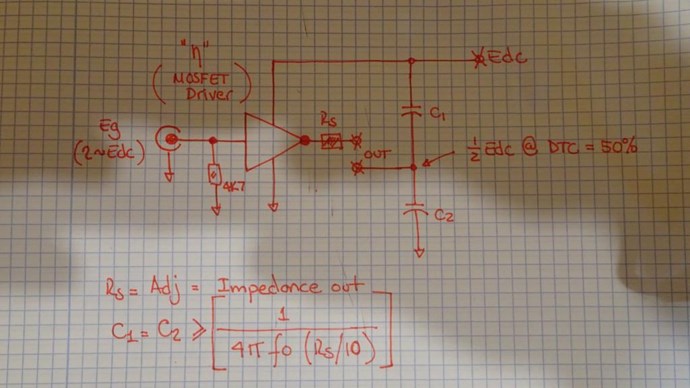
A drawing of the schematic that I present to you freehand

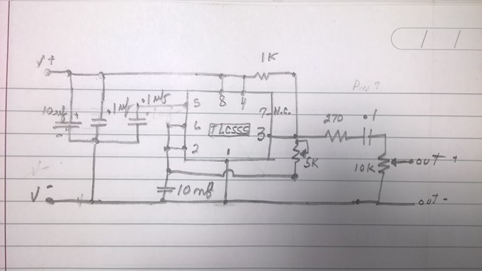
It can be easily changed by changing a single resistor and a single capacitor.

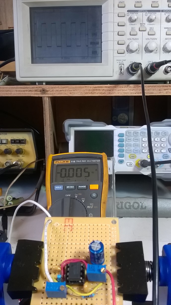
5 ma on 9 volts battery here


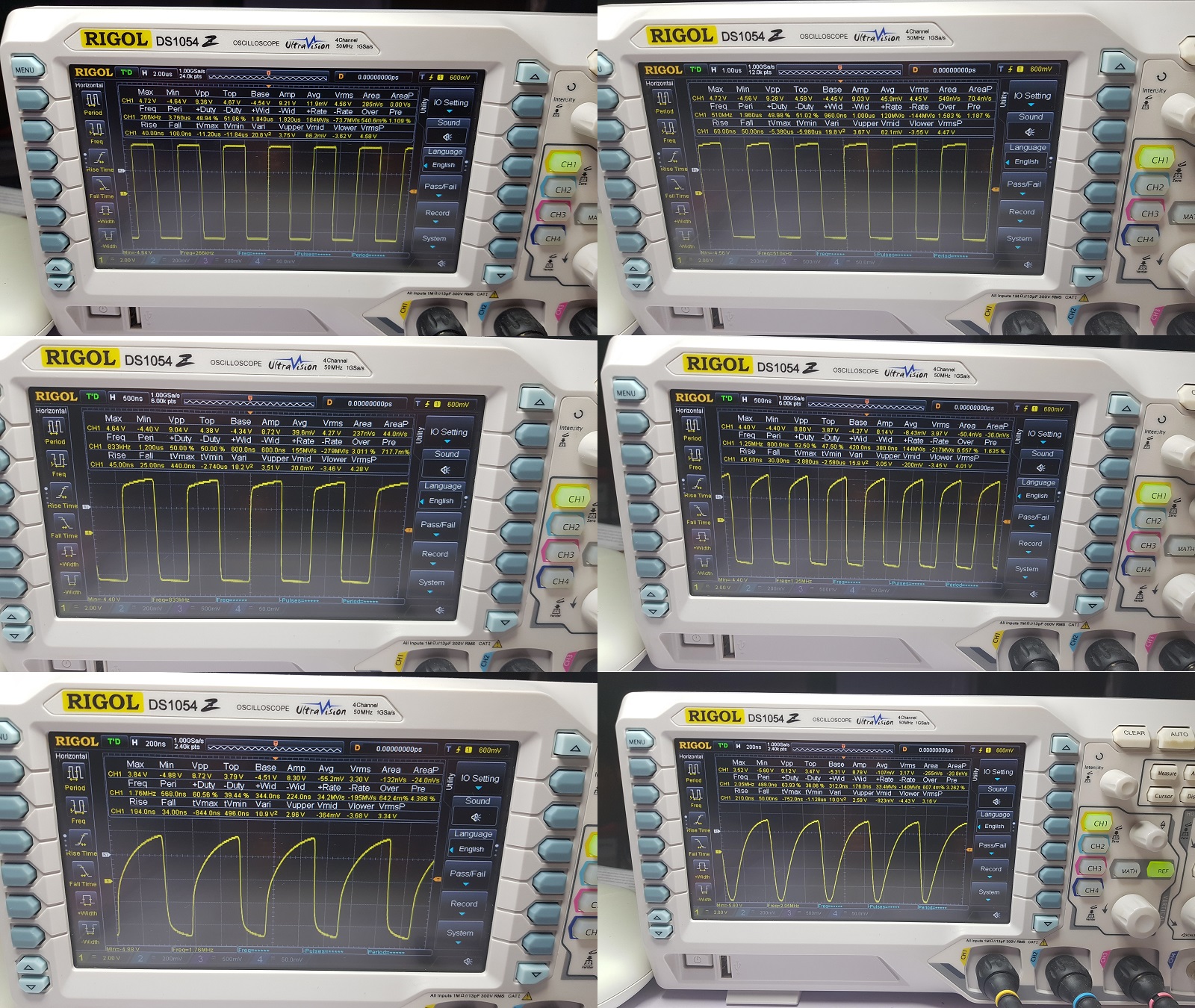
The particularity of this oscillator is that the output voltage changes from positive to negative through zero in the center. This is the AC square wave shape.

Most of these freely sold circuits are above zero volts they are only DC square wave and could not be use for experimentation.

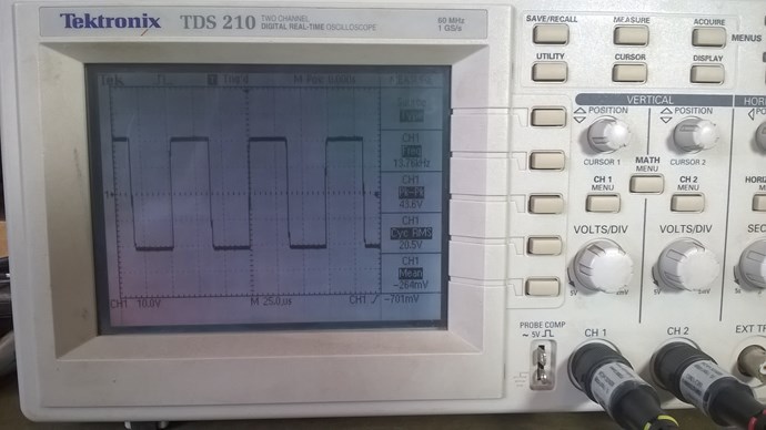
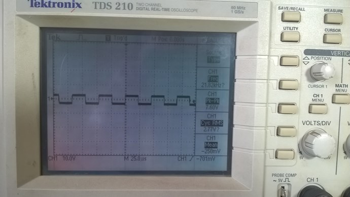
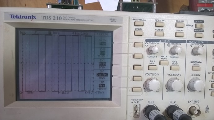
Very low or high amplitude at your choice


This way you are isolated from the electrical network and have greater freedom of measurements without ground return.

 I also hope for those who would like to join us and experiment with us and do not have a function generator, this is the ideal opportunity, easy to assemble and inexpensive.

Jagau

  • Liked by
  • AlteredUnity
  • Inception
Fighter posted this 21 October 2020

Thanks for the help !

"If you want to find the secrets of the universe, think in terms of energy, frequency and vibration."
Nikola Tesla
  • Liked by
  • Inception
Fighter posted this 30 October 2020

Hi Jagau,

I'm currently building the oscillator and I have two questions.

The first question is: what's the value of this capacitor ? The same 1 uF like others ?

And the second question is: according to the specs TLC555CP can provide directly about 100mA which I think is more than enough to drive the primary coil for QLED devices. Would be wise to use it this way or should I add a MOSFET on output so TLC555CP will command it for supplying the current for the primary coil ?

Thanks for your guidance.

Note: in my build I added a 2000 uF electrolytic capacitor on the input of the circuit for a later use, it shouldn't have any impact on the oscillator's functionality. I intend to try to use it later for charging it from the secondary coil (QLED-style).

"If you want to find the secrets of the universe, think in terms of energy, frequency and vibration."
Nikola Tesla
  • Liked by
  • Inception
Jagau posted this 30 October 2020

Hi fighter


For the first question, the capacitor is a 0.1 uf or 100 nf


For the second, the manufacturer tells us that this integrated circuit allows you to easily make a 100 ma well with a 10 ma power supply within these limits if your leds do not exceed 100ma I do not think there is a problem.

According to this charter, you can even go up to 300ma but the IC will heat up,

Anyway, the output is fully compatible with cmos, ttl and mos, you can always increase your power.

For the 2000uf capacitor at the input, we normally use  between 1-100uf  with 0.1uf in parallel. The small capacitor is used to cut high frequencies which could degrade the use of the integrated circuit and the large capacitor for the low frequency line filtering.

I imagine you want to use it as a future power source instead of a battery?

Jagau

  • Liked by
  • AlteredUnity
  • Inception
Fighter posted this 30 October 2020

Hi fighter

For the first question, the capacitor is a 0.1 uf or 100 nf

Got it.

For the second, the manufacturer tells us that this integrated circuit allows you to easily make a 100 ma well with a 10 ma power supply within these limits if your leds do not exceed 100ma I do not think there is a problem.

According to this charter, you can even go up to 300ma but the IC will heat up,

Anyway, the output is fully compatible with cmos, ttl and mos, you can always increase your power.

I think I'll go without MOSFET for now.

For the 2000uf capacitor at the input, we normally use  between 1-100uf  with 0.1uf in parallel. The small capacitor is used to cut high frequencies which could degrade the use of the integrated circuit and the large capacitor for the low frequency line filtering.

I imagine you want to use it as a future power source instead of a battery?

Jagau

I also kept the small capacitor in place, the bigger one is additional.

That is correct, the bigger capacitor will be the power source in the future, that's the plan.

Thanks for the guidance !

"If you want to find the secrets of the universe, think in terms of energy, frequency and vibration."
Nikola Tesla
  • Liked by
  • Inception
Fighter posted this 09 November 2020

This is my build of Jagau's AC Oscillator.

I know that in my build I pushed the frequency range to the limits.

You'll see I placed two sockets so the 10nF capacitor and the 5K variable resistor can be easily replaced with different values to change oscillator's frequency range:

The only modification I made was to add a 2200uF/25V electrolytic capacitor on input.

In the following scope images I'm using a 9V battery on input, an 1nF capacitor and an 2.2K variable resistor which is offering a range starting at 266KHz and ending at 2.05MHz. The scope probes are connected directly on output and there is no other load.

Frequencies shown in the images are (in order): 266KHz, 510KHz, 833KHz, 1.25MHz, 1.76MHz and 2.05MHz.

You'll notice that as I'm forcing the frequency up the square wave is becoming deformed, my electronics knowledge is limited so I don't have a explanation for this but I suppose there is one and this is normal.

Also depending on frequency there seems to be a slight difference between the positive voltage (Max) and the negative voltage (Min), also don't know the cause for that:

But we don't need MHz frequencies for our experiments so it's an excellent oscillator for experiments were real AC is needed even if we're using DC for input.

Just want to thank to Jagau for this excellent AC Oscillator, I intend to use it in QLED-type experiments.

"If you want to find the secrets of the universe, think in terms of energy, frequency and vibration."
Nikola Tesla
  • Liked by
  • Inception
Jagau posted this 09 November 2020

Hello fighter
nice job, you now have one more tool in your lab, I often use it too.
A recommendation from the manufacturer is this in section 10.1:

10.1 Layout Guidelines
Standard PCB rules apply to routing the TLC555. The 0.1-μF ceramic capacitor in parallel with a 1-μF electrolytic
capacitor must be as close as possible to the TLC555. The capacitor used for the time delay must also be placed as close to the discharge pin. A ground plane on the bottom layer can be used to provide better noise immunity and signal integrity.

For the question of lowering the negative side you will have to make a power supply circuit with a virtual ground, this will correct the problem of voltage difference.
I recommend this simple and efficient one for all the ICs that you will have to use in the future.

This circuit is not mine, it works very well I use it in my setup

Jagau

  • Liked by
  • Inception
Jagau posted this 01 December 2020

Hi all

One of the problems encountered nowadays when working with instruments connected to the grid is that often we have to isolate them or even make them work with inverter on batteries. The second next problem is that the batteries drain quickly because the devices draw a lot of current.

To solve this problem with the oscillator above we can already solve the first part of the problem given that it operates at very low voltage and current.

For the other problem I am building an instrument amplifier which I believe will solve the second problem, having a little more power in the square output waveform.
The schematic of the one I am building.

When it is ready I will let you know and we can use it together with the square oscillator with more latitude in the power and being free and well isolated  from the grid .


Jagau

  • Liked by
  • Inception
YoElMiCrO posted this 01 December 2020

Hello everyone.

@Jagau.

If I may...
This circuit meets the requirements you need.

As you can see, once you find the necessary serial impedance
and the working frequency, you can replace the resistor with an inductor,
in this way the energy you lost in it becomes null and void!.
I hope it'll do you some good.

YoElMiCrO.

  • Liked by
  • Inception
  • Vidura
Jagau posted this 01 December 2020

Thanks Yo


 The goal of having a voltage amplitude only of the square wave with a very high impedance input so as not to alter it and also a low consumption at the input.

Thank you will analyse this capacitive divider too if it will do the job


Jagau

  • Liked by
  • Inception
Jagau posted this 03 December 2020

Ok, the differential driver that I proposed has a slew rate too low, it works well up to 10khz but after that it is too slow for the rate of change (slew rate), it is a bit of the problem of most of have operational amplifiers.


So Yoelmicro

I'm going to look at your circuit you offered me, could you please explain me more precisely the proposed circuit.

i thought it was a negative resistance circuit?

I just want to increase the amplitude of the square wave oscillator without distorting it

Thank you Yo

P.S. just a precision when I speak of frequency not exceeding 10khz I am talking about the differential amplifier and not the tlc555 oscillator which easily goes up to 200khz and more


Jagau

  • Liked by
  • Inception
Close