Hello Community,
Since years a lot of people try to replicate the don smith earth system without luck as I see. So I just want to ask what exactly we know about the machine ? I will concentrated on that what I can see in the original Materials. the Raw input so to speak...
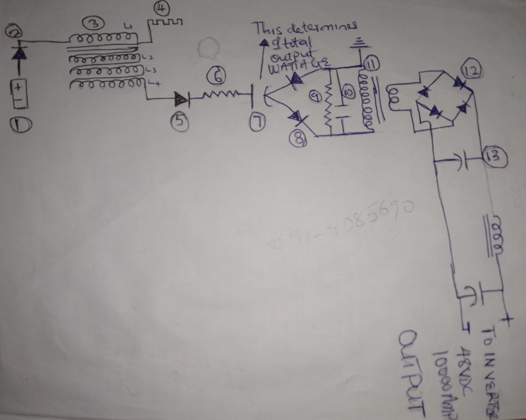
There is a schematic on the net which should be "the device". later I found out there are 2 different circulating. It seems it comes from a patent application but i cant find the patent granted.
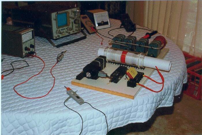
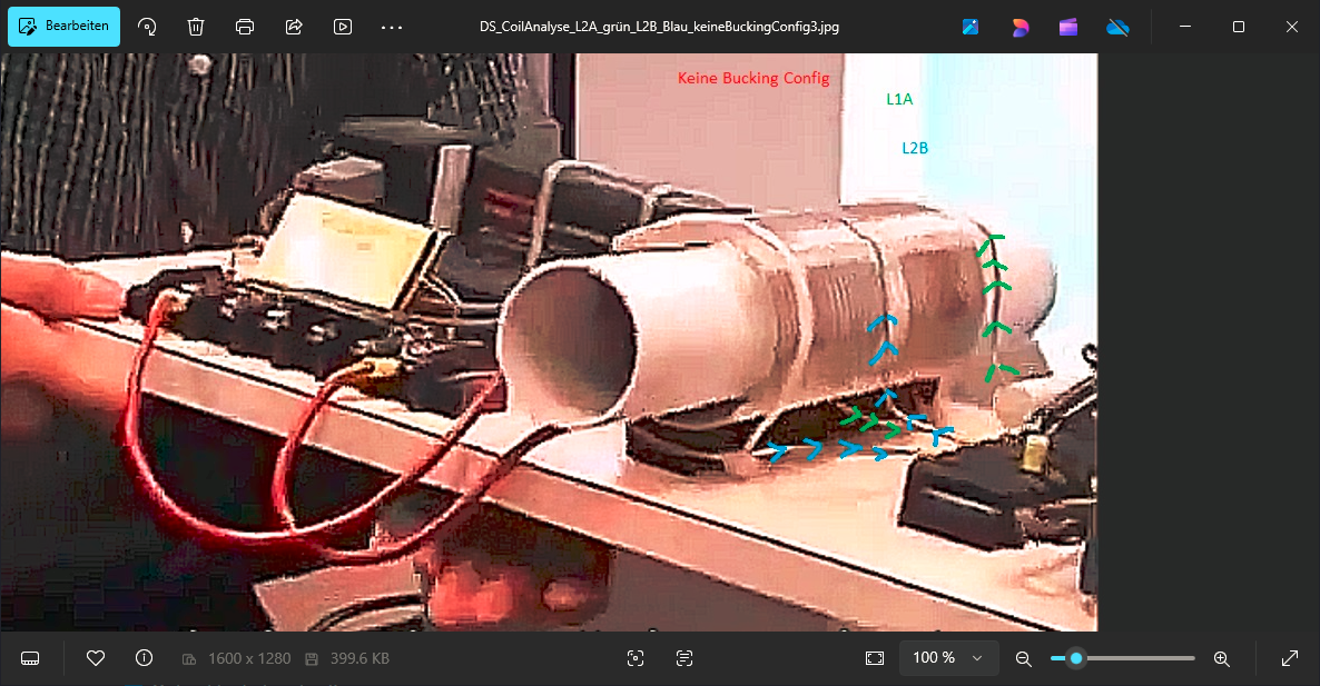
So on the Image above I cannot see a L3 output Coil ? inside the tube ? where are the wires for L3 then?
since they differ so much (L3 / Parts omitted...) I don´t upload the various ones . this seems to be misleading to understanding as someone has edited them for confusion.
in one of the Lectures he stated , that parts are missed from disclosure because of investors interests and his security.... but it should be easy to figure out for an HAM operator. Ok. My ham operator told me he don´t know..."
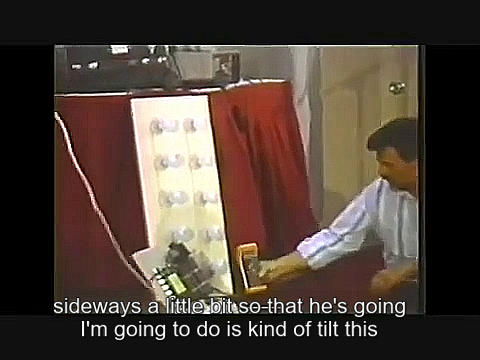
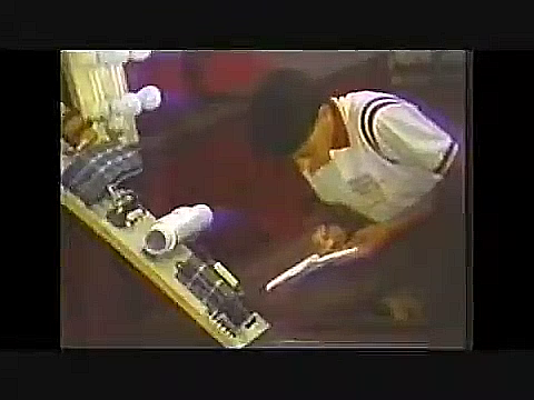
there is a lecture where he Lit 1000 W of indecant Lamps on a Board, while his Demonstrator sits left side from the board...But I don´t know if this was powered from this board or a suitcase.
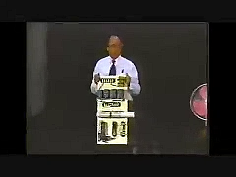
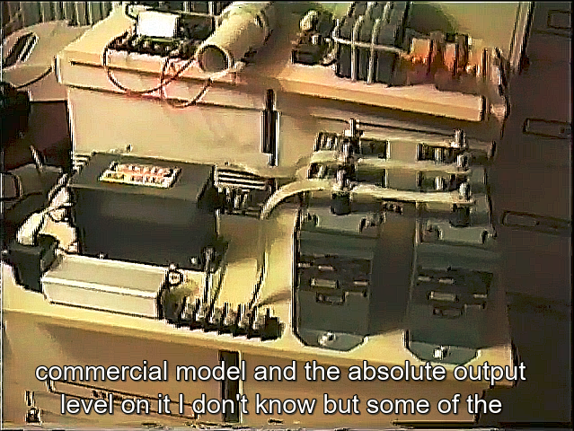
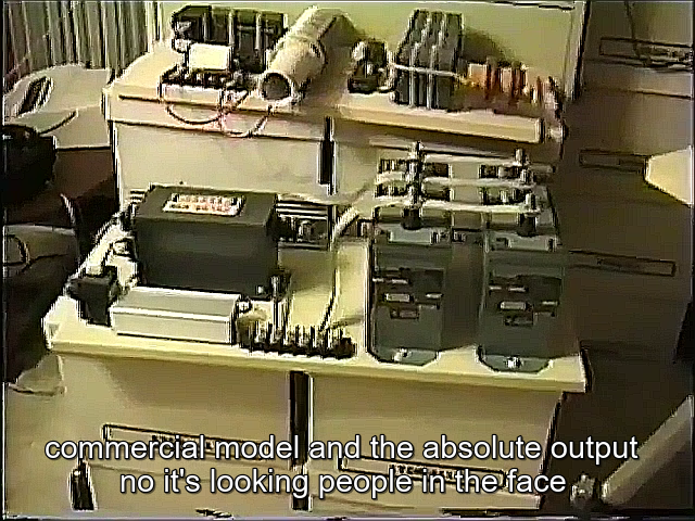
how big is this MONSTER:
for my it looks like a demonstrator only to look - not the device which powered the light bank ?
what you are thinking ?
I didn´t found ANY good Image of this UNIT on the net ! nowhere.
As I found Dons Website in archive.org , every backup has the big Image of this REMOVED !!
no joke ! all his images are since the 90ties here in archive. Not this unit ! damn
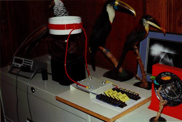
OK What we learn: NST , OILCAP, Primary LC (yellow big CAP) - and white shimmering WHAT ?
where is the battery here ? No powersupply ? Why ?
Why the white core goes away from panel ?
is there a Barker coil in front of device on the Floor ? with 8KV yes ? I cannot believe this.
this we all know Ok...
and the people try to draw schematics from that what they see. I found in the office video exact the device which was used back then:
(in the upper left part)
and lower side: the HIGH Power DSE V3
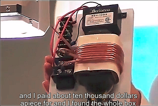
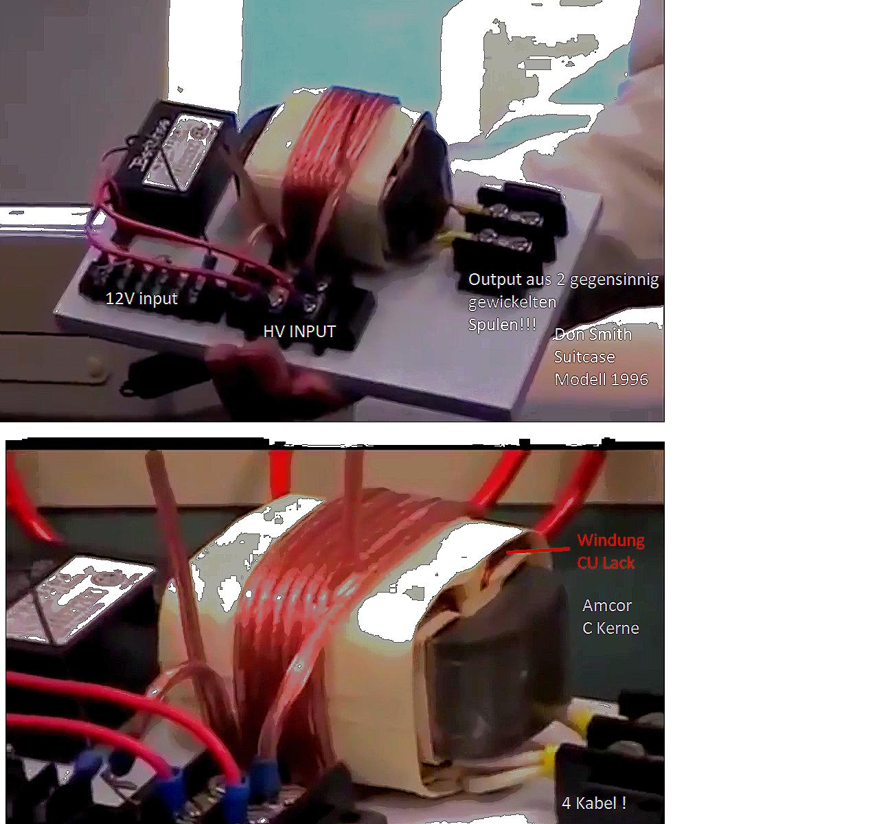
On inventors Weekend Don told us, that the Amcore transformer is exactly the device he showed 1996 in the suitcase ! But this is a completely different device than the Earth system he showed 1996 in my opinion.
So what we exactly know for sure about this device ?
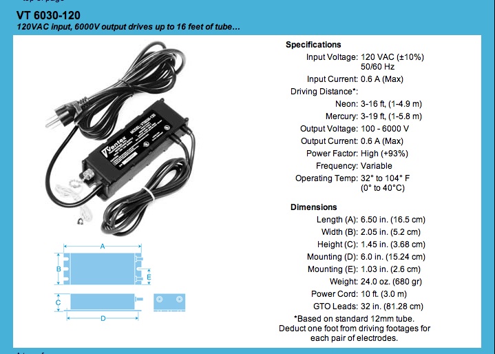
The NST is a short Circuit ! No Sparkgap, no charge Capacitor -> OK
then:
if you put in on the same speakerwire (L1 which goes arround the AMC) and create a short ! VERY BAD ! Don´t do that !! you kill the NST in seconds.
OR: if you use it Bifiar as we can see -> you supply the 2 wires with HV one next to the other
AND LET THE ENDS OPEN. If my theory is right you have a cap coupling in the other coils (E Field)
but this is theory and I was not able to confirm on testbench at the moment.
Found another image:
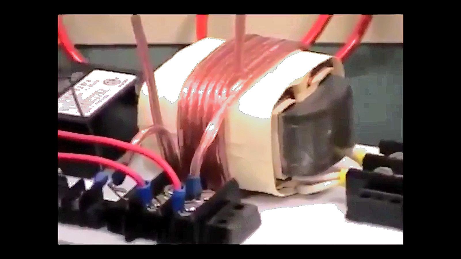
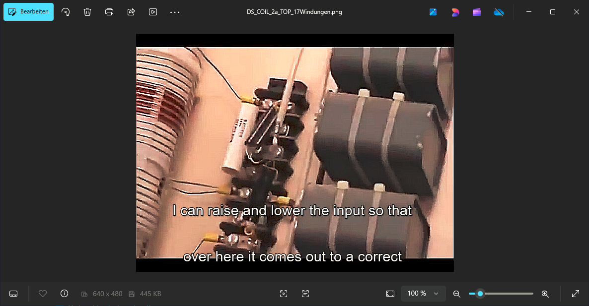
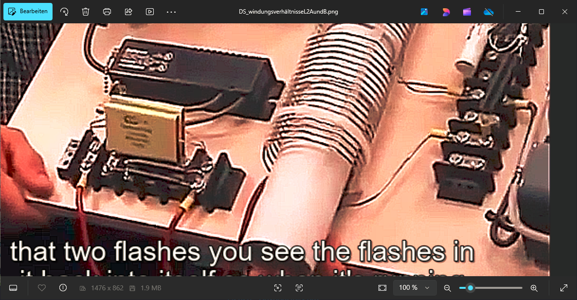
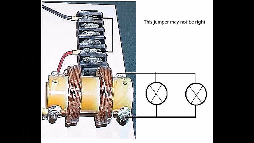
How are the coils winded ?
Could you see how the wires are going from and to ?
my friends told me the could see its POC style. But I´m not sure. and IF yes . which one ?
l1 to L2
or L1A to L1B to L2
or L2A to L2B to L1 ? Crazy...
I hope this is not boring ? sometimes its good to brainstorm and check the way we are of...
some Images from my archive:
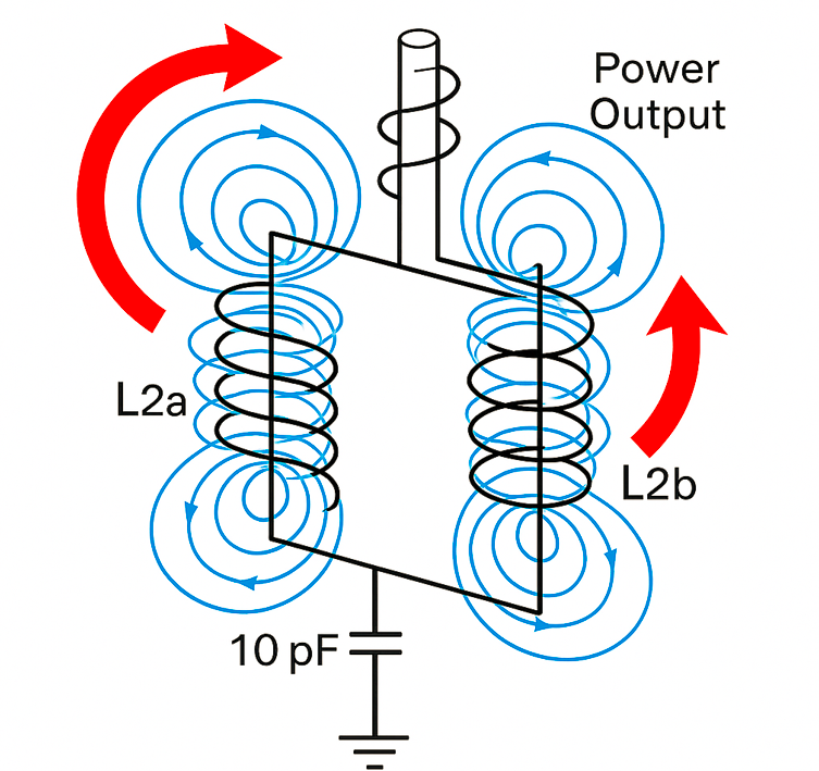
the cap should go between L2A and L2B on the middle TAB and goes to Earth . This should do a DAM for the ground electrons. Because the resistance is High for the rotating electrons in the L2A/B Reactor.
But this system needs then a third coil (L3) loose coupled (to not affect the NST Supply) to pull the electrons out of the Tank for using with Capbank / Loads
Inductive power out with diodebridge under metal and smoothing caps in parallel.
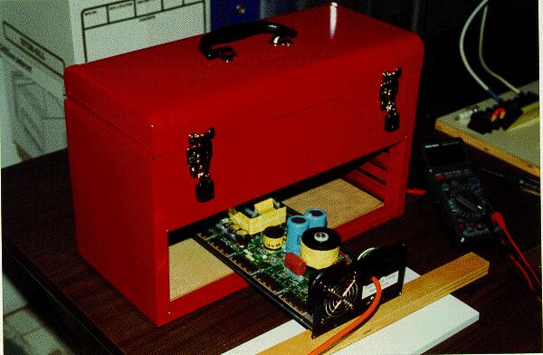
Coke Machine Japan. Power inverter pcb. seems to be out of the box. not self builded. whats next to it on the table ? the rest of the ambient device ?
