What we know exactly about Don Smith Device

  • 1.5K Views
  • Last Post 2 hours ago
HansKammler posted this 26 September 2025

Hello Community,

Since years a lot of people try to replicate the don smith earth system without luck as I see. So I just want to ask what exactly we know about the machine ? I will concentrated on that what I can see in the original Materials. the Raw input so to speak...

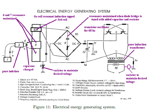
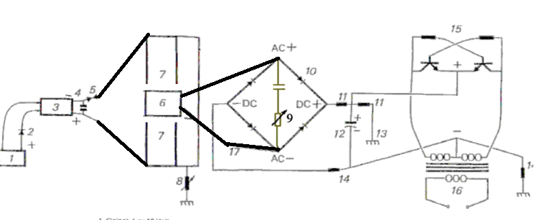
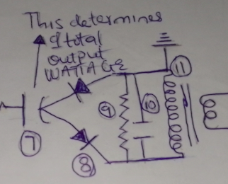
There is a schematic on the net which should be "the device". later I found out there are 2 different circulating. It seems it comes from a patent application but i cant find the patent granted.

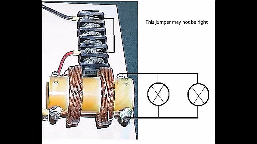
So on the Image above I cannot see a L3 output Coil ? inside the tube ? where are the wires for L3 then?

since they differ so much (L3 / Parts omitted...) I don´t upload the various ones . this seems to be misleading to understanding as someone has edited them for confusion.

in one of the Lectures he stated , that parts are missed from disclosure because of investors interests and his security.... but it should be easy to figure out for an HAM operator. Ok. My ham operator told me he don´t know..." 

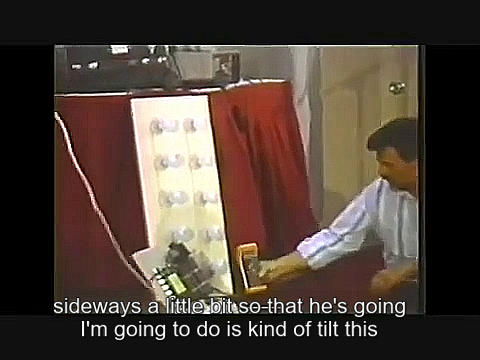
there is a lecture where he Lit 1000 W of indecant Lamps on a Board, while his Demonstrator sits left side from the board...But I don´t know if this was powered from this board or a suitcase.

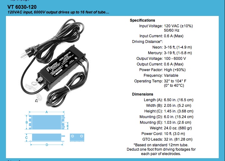
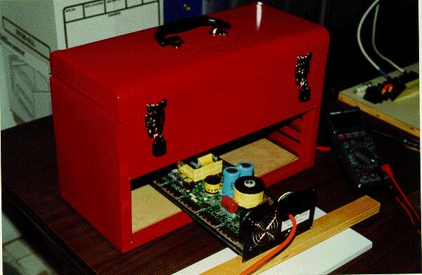
how big is this MONSTER:

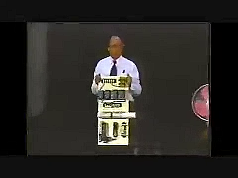
for my it looks like a demonstrator only to look - not the device which powered the light bank ?
what you are thinking ?

I didn´t found ANY good Image of this UNIT on the net ! nowhere.
As I found Dons Website in archive.org , every backup has the big Image of this REMOVED !!
no joke ! all his images are since the 90ties here in archive. Not this unit ! damn

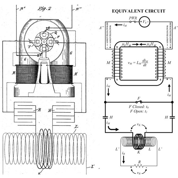
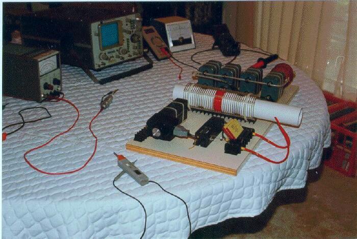
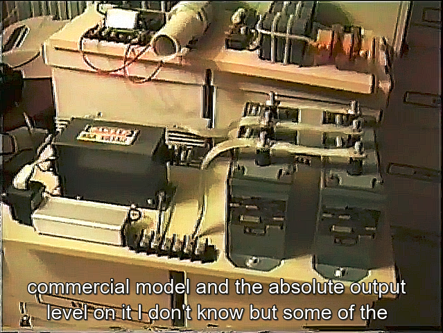
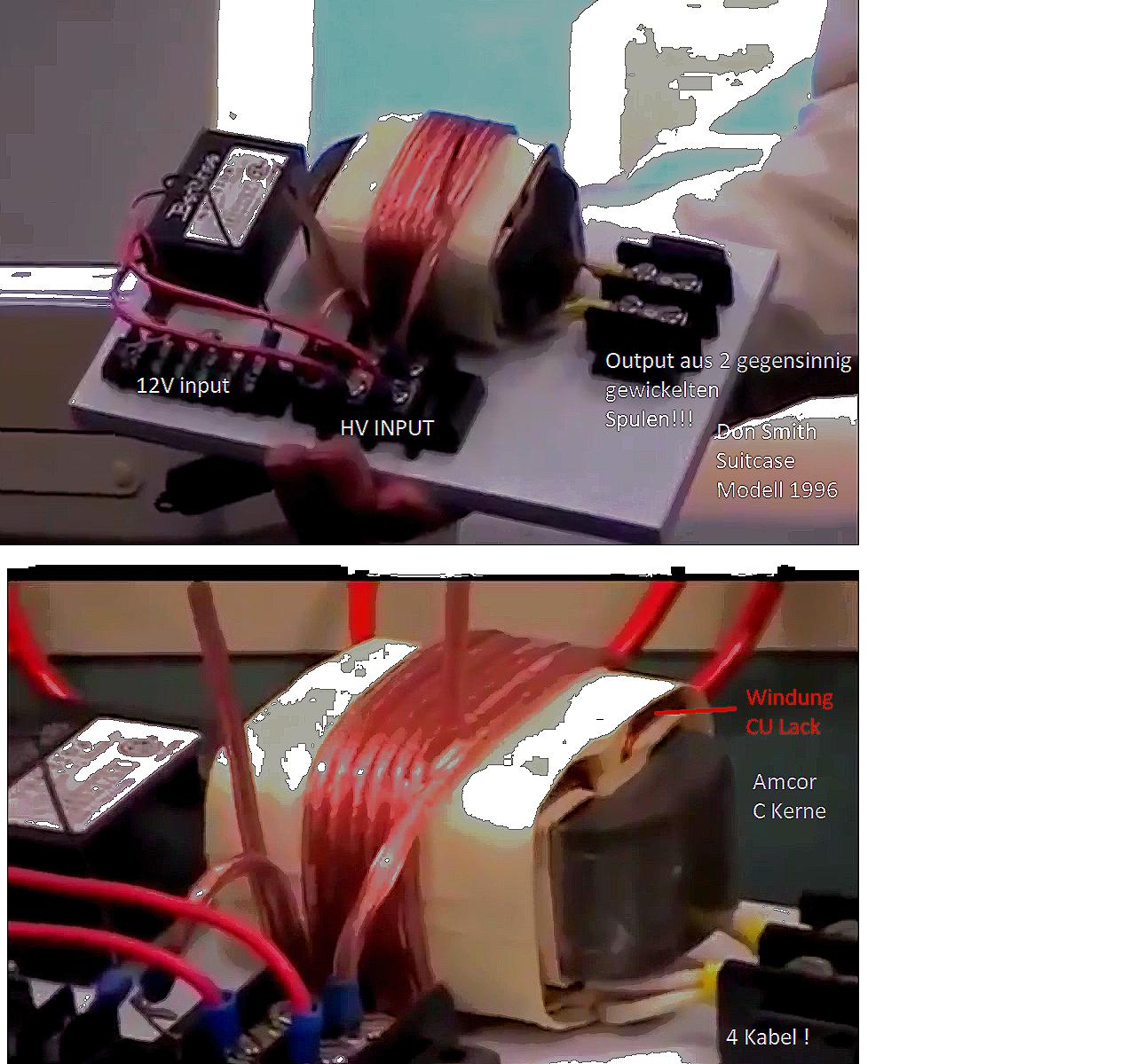
OK What we learn: NST , OILCAP, Primary LC (yellow big CAP) - and white shimmering WHAT ?
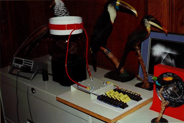
where is the battery here ? No powersupply ? Why ? 
Why the white core goes away from panel ?
is there a Barker coil in front of device on the Floor ? with 8KV yes ? I cannot believe this.

this we all know Ok...


and the people try to draw schematics from that what they see. I found in the office video exact the device which was used back then:


(in the upper left part)

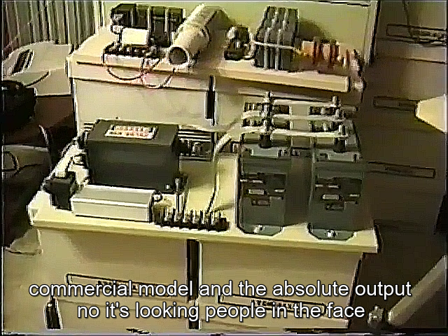
and lower side: the HIGH Power DSE V3

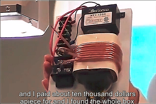
On inventors Weekend Don told us, that the Amcore transformer is exactly the device he showed 1996 in the suitcase ! But this is a completely different device than the Earth system he showed 1996 in my opinion.

So what we exactly know for sure about this device ?

The NST is a short Circuit ! No Sparkgap, no charge Capacitor -> OK 
then:
if you put in on the same speakerwire (L1 which goes arround the AMC) and create a short ! VERY BAD ! Don´t do that !! you kill the NST in seconds.

OR: if you use it Bifiar as we can see -> you supply the 2 wires with HV one next to the other
AND LET THE ENDS OPEN. If my theory is right you have a cap coupling in the other coils (E Field)
but this is theory and I was not able to confirm on testbench at the moment.

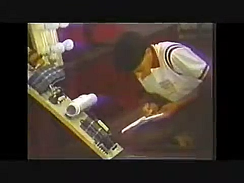
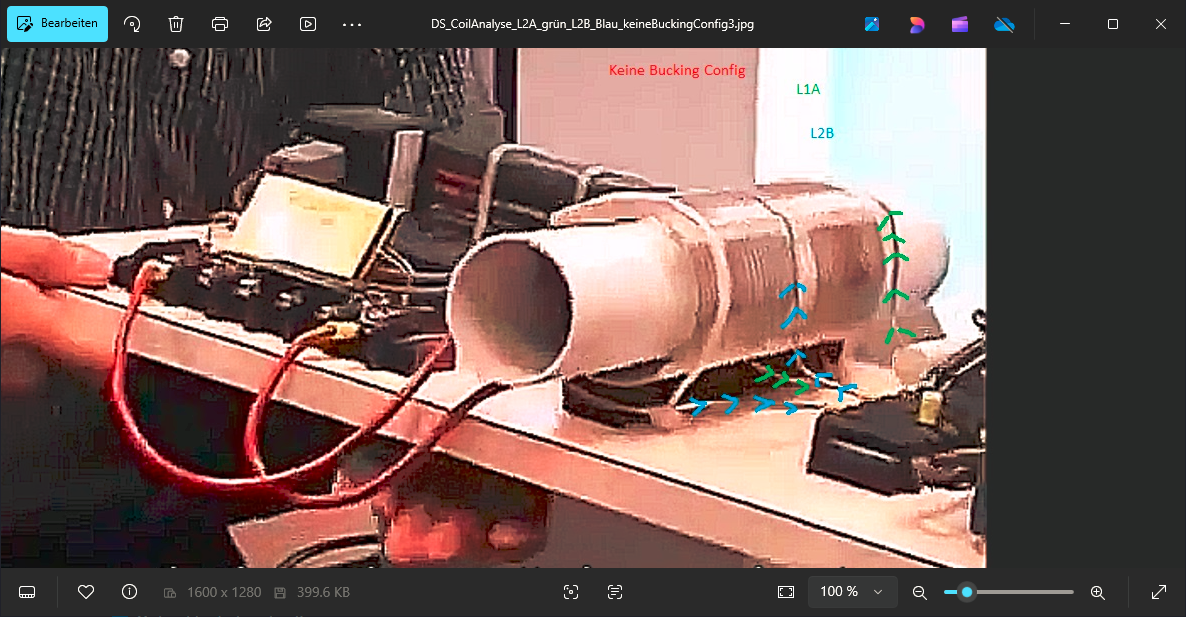
Found another image:


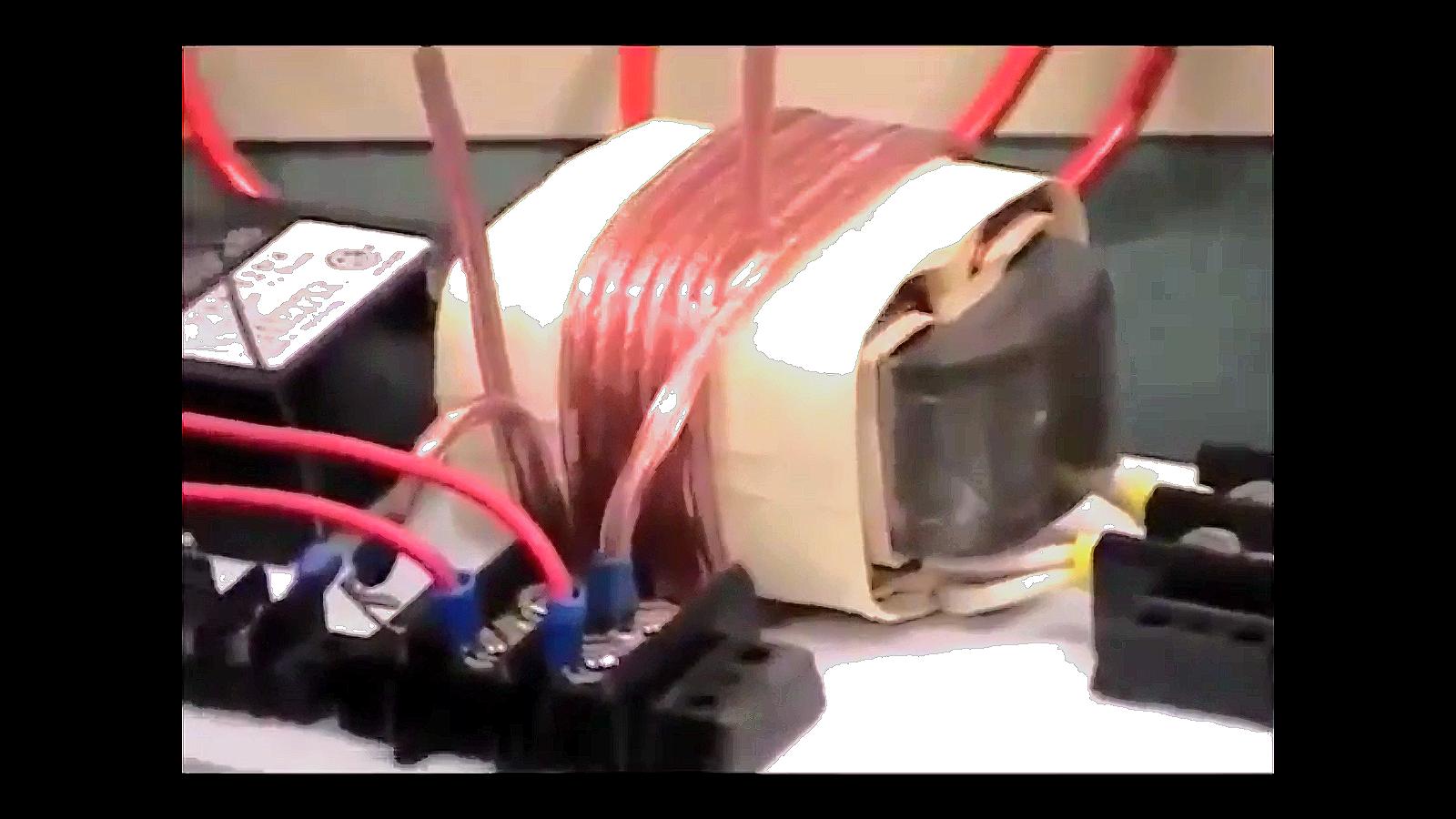
How are the coils winded ? 

Could you see how the wires are going from and to ? 
my friends told me the could see its POC style. But I´m not sure. and IF yes . which one ? 
l1 to L2
or L1A to L1B to L2
or L2A to L2B to L1 ? Crazy...

I hope this is not boring ? sometimes its good to brainstorm and check the way we are of...


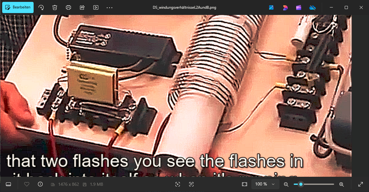
some Images from my archive:

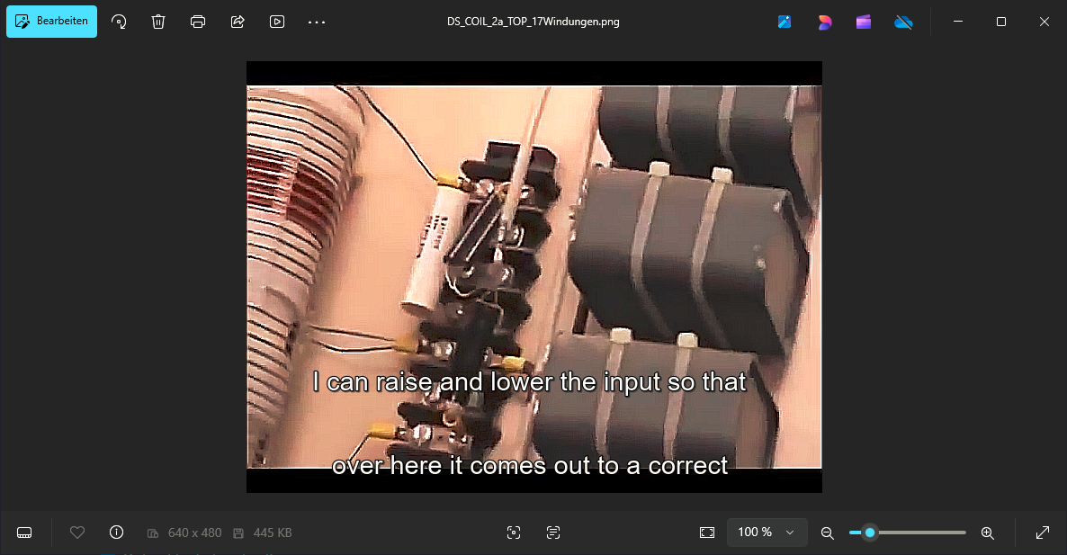
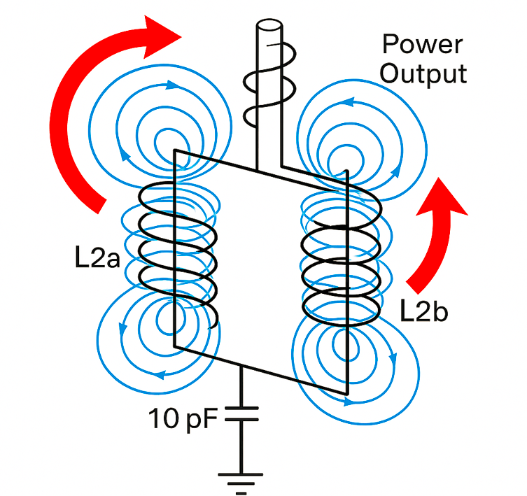
the cap should go between L2A and L2B on the middle TAB and goes to Earth . This should do a DAM for the ground electrons. Because the resistance is High for the rotating electrons in the L2A/B Reactor.

But this system needs then a third coil (L3) loose coupled (to not affect the NST Supply)  to pull the electrons out of the Tank for using with Capbank / Loads 

Inductive power out with diodebridge under metal and smoothing caps in parallel.

Coke Machine Japan. Power inverter pcb. seems to be out of the box. not self builded. whats next to it on the table ? the rest of the ambient device ?

Attached Files

Darediamond posted this 3 days ago

Replying To: Jagau

I did not make the video of it while in operation.

andy2 posted this 2 days ago

Quoting:Darediamond

The Don Smith Effect Generator Is What You All Should Build. It is straight forward and of 2 stages. Stage one is the Serially Connected windings Voltage Step Up High Frequency Driven Low Voltage Input Transformer With A Primary Winding of Calculated Natural Frequency In View Of it Wire Length which Don Smith talked about Himself. Stage 2 is the Forced Resonance Step Down Transformer that can either be made with Iron Core (50hz/60Hz) or Ferite Core (High Frequency). If you use a 60hz Core, you must use a Combination of calculated capacitor and resistor on it primary leads to bring down the incoming high frequency from the Total OUPTUT wattage Determinant Capacitor Bank back to 60hz. But of you use a Ferrite Core, you just need to add the calculate cap and resistor to tune it to the High frequency your DC Power Damming Caps are charging at and make sure you use a Pi Filter at it output to get a PURE DC that you can use to charge your battery banks and or High Power Inverter or Direct Current Motor etc. Typing sucks; it is not easy at all. So If you need indepth knowledge on How To Build The Don Smith Effect Infinite Output Electric Power Generator, reach me via WhatsApp on +23470 60 578 569

@Dare

Thank you for the info. What is number #4 in your schematic  - square switching frequency to ground or antenna?

A.

Jagau posted this 2 days ago

When comparing Tesla's circuit to Don Smith's, I can't help but make some comparisons.

Tesla's:

The two Tesla coils in opposite phase is like 7 in D. S.  K is 6 and so on.


Don Smith's:

Two coils 7 in opposite phase, fused and amplified by a third coil with the help of capacitors and tuned to the resonant frequency. The result is spectacular when you remove 6A completely and connect 3 directly to the two extremity of 7 and you harvest on 6 to the bridge.

A picture of my setup, 8 is adjust like zero transformer, we need only radiating voltage without current. On ech side of coil 6 we have two AV plug formed by the bridge.

You get between 40 and 50 times the input voltage this way; for an input voltage of 1kV, you get between 40kV and 50kV. Exactly as Tesla did in the comparative circuit above.
This is an extremely dangerous circuit and involves very high voltages.

Jagau

Darediamond posted this 2 days ago

Replying To: andy2


Yeah it is the Signal Generator and N-Channel MOSFET 

https://www.aliexpress.com/item/1005003342689423.html

If anyone needs indepth explanation on how this Exact DON SMITH EFFECT GENERATOR WORKS, reach me via WhatsApp +2347060 5 7 85 69

Darediamond posted this 2 days ago

Replying To: Jagau

Infact, you do not even need to input 200V let alone 1000V or higher to get 40KV or more if you follow The DON SMITH EFFECT GENERATOR CIRCUIT which is actually DON'S main Invention unlike the earlier ones which are modernized Tesla's Inventions. Telsa uses mechanical components which are what are available in His time. Don simply replaced those components with modern ones. But The Don's Smith Effect Generator is Don's own and it it the MOST POWERFUL HANDS DOWN because you are allowed to use your Secondary to harvest the Back E.M.F of the Primary etc.

Darediamond posted this 2 days ago

Replying To: Jagau

You don't need the spark gap at all! Don himself revealed that He have to put some unneeded components in the Gen Circuit and on display to satisfy the powers that be or "THE ESTABLISHMENT"!!

baerndorfer posted this 2 days ago

we can assume HV/HF resonance between coil and capacitor. resistor is maybe to 'tune' frequency a bit down. the avramenko-plug design makes sense, the input is also a resonating sine. if thouse conditions are set, the output should be as don described. 

but i have not reached it yet 😎

regards

B

Jagau posted this 2 days ago

One thing is certain: what I've published here works. I've tested it at low voltage and gradually increased voltage and it works exactly as described. A few people here have seen the results, which is why I'm issuing the high-voltage warning.

Don Smith has often said that his ideas came from what Tesla produced. Tesla worked with such high voltages that only Eric Dollar managed to reproduce some of them.

Yes, it is possible not to use a spark gap, but what must replace the SG is a somewhat special circuit carefully constructed to produce very short rise time pulses. Regarding the voltage, DS used 8kV in its laser modules. What's important is the voltage, not the current, with a very, very rise time pulse.

DS never published its diagrams exactly as they were; we know that. They gave the general outline, and it was up to us to read between the lines, of course. 

Instead of posting your WhatsApp number, show us here what you can do. The purpose of this forum is to share. I would very much like to learn about and discuss your DS projects with you and all here, learn together.


@ Bearndorfer:
Yes, D.S. was working on RF frequencies of 220 MHz, which is why he had good results at those frequencies. The higher the frequencies, the faster the capacitors charge. 220 Mhz is in VHF band.

Jagau

Darediamond posted this 2 days ago

Replying To: baerndorfer

There is nothing to assume in the DON SMITH EFFECT CIRCUIT I finally connects all of it each STAND ALONE DOTS. The Circuit I presented is Don's Circuit nearly 100%. The only area at which I modified it is in the First Transformer with Multiple Serially Connected Secondaries to infinitely multiply the one wire output voltage from an input voltage of just 98Volt DC. There is a better way of winding the said Power Amplifying Natural Resonance Switched or Oscillates Transformer which would require anyone who wishes to try it to build a simple wooden Manually Operated Machine but it is not compulsory although, it is the only way I have found to easy wind multiple Wires at a go to multiply the voltage CRAZILY!! Anyways, it is not critical because the Power Determinants Capacitors can also be Increased in Size you only need to modify the Time Constance Resistor if you do. Also the High Frequency is additionally there too. It effect on the capacitor is to rapidly charge the caps even if they a Super Capacitors. So you can even use a single secondary under primary of Power Amplifying Transformer and still generates Power In the MegaWatts Range because of RESONANCE which you must maintain in each stage of the Don Smith EFFECT Capacitive Transformer Infinite Energy electric Generator. Don owns the circuit BUT he never draw the Circuit Completely the way you all have the Opportunity to get it now from me after I Practically linked all the dots he scattered in so many places online. There are other things that I can't show anyone on here except via live video call. So if you wish, call and if you don't keep trying to figure out.

Darediamond posted this 2 days ago

Replying To: Jagau

According to Don Smith in some of the earlier said individually dots of his that I PRACTICALLY LINKED TOGETHER AT LAST, the determinant of your Resonant Frequency is the Length of Wire In the Primary Winding Of the First STAGE POWER AMPLIFYING TRANSFORMER. Don in his own setting used a readymade transformer. But I in my own setting choose to DIY it and it works WICKEDLY as it opens a new door of discoveries. Do you even know that you can cancel the Step down Transformer and use Diode Capacitor Combination to Step-Down the voltage on the power determinant set of Caps? Well that is not Don's system it is actually Mine and I shared the circuit online at overunity some years ago and someone contacted me from Georgia ia WhatsApp that it works exactly the way I showed it.

Don said that use Natural Frequency of a length wire to make thew L1 Winding. You do not even need Frequency of 100Khz let alone 1 megahertz nor a gigantic 200 megahertz because even at 45khz, a capacitor of 10 Farad would charge up in a twinkle of a millisecond over and over again. And that against where thee Full and Overflow Current Lies!!! I am not just talking here, I have walked the talks and see that Don did not lie. And according to Him, you need no complex set ups nor tools nor unnecessary ASSUPTIONS because though He has to reveal it bit by bit here and there, HE HAS GIVEN IT ALL OUT how to build the SUPER OF SUPER POWERFUL Don Smith Invented Infinite Energy Electric One Wire Output Don Smith Effect GENEERATOR.

Resonance 1 : Natural

Resonance 2: Time Constant = T= RC

Resonance 3: Force Resonance

Close