ZPM Related Questions

  • 1K Views
  • Last Post 27 June 2023
Fighter posted this 10 June 2023

In order to keep the ZPM replications threads clean I've created this thread when questions can be asked and discussion related to ZPM's functionality can continue.

We can discuss here about the standing waves on ZPM's output, the waves propagation in the core and any subjects not directly related to those ZPM replications.

Regards,

Fighter

"If you want to find the secrets of the universe, think in terms of energy, frequency and vibration."
Nikola Tesla
  • Liked by
  • Shadow_
  • Vasile
Order By: Standard | Newest | Votes
Fighter posted this 10 June 2023

In order to keep the ZPM replications threads clean I've created this thread when questions can be asked and discussion related to ZPM's functionality can continue.

We can discuss here about the standing waves on ZPM's output, the waves propagation in the core and any subjects not directly related to those ZPM replications.

Regards,

Fighter

"If you want to find the secrets of the universe, think in terms of energy, frequency and vibration."
Nikola Tesla
  • Liked by
  • Shadow_
  • Vasile
Atti posted this 27 June 2023

Another example.
Here you can also see that the AMCC core is equipped with additional coils. 
In the first part you can see that the mains frequency is superimposed on the mains supply by the capacitors and the earthing. This must be taken into account. However, in this arrangement the current strength is almost unaffected.  There is only a change if I place the earthing at the point where the two coils meet!  Then you can measure the high voltage with the neon lamp. This is clearly shown in the second part. Here the test is carried out with a machine tool battery. At this setting, there is a very small decrease in the intensity of the current drawn and an increase in the voltage of the bulb. In this case, the high voltage appears everywhere.

So when using earthing ( either with battery or with some laborator power supplies), the capacitive way of closure is clearly visible. There are times when it causes an increase in current and times when it causes a decrease in current. 
As you can see this is shown when the neon light on the foot of the Mosfet Drain is on. 
I could not get this result without additional coils.


Fighter posted this 27 June 2023

Quoting:AlteredUnity

can any of the successful replicators run their ZPM from a simple buck/boost converter, they usually have displays of V and A, sometimes Watts. I know they wouldn't be accurate, though very useful, and they are very cheap and will show if different power supplies would change the operation.

Buck/boost converters have their own coils. Think about how those coils will affect the functionality of ZPM.

Anything added in the circuit have effect on the functionality. Even the probes of the oscilloscope added to the circuit modify the resonance frequency of ZPM, when I do that I need to find the new optimal resonance frequency (usually at a few KHz distance).

Now talking about input, I'm adding a fragment from my post here:

Still, I used an more advanced power meter which (I'm quoting from its specs): "Acts like a wire so doesn't affect model's performance. Precision Alu-Chrom current sensing resistor, with only 0.001Ohms resistance and circuitry that draws only 7mA Uses DSP to increase ADC resolution and differential measurement amplifiers to increase noise immunity. Powerful, 8MIPS micro-controller.". I "forced" ZPM out of the optimal/resonance frequency so the consumption would be higher because the wattmeter is not built to measure currents lower than 0.100 A. and it confirmed the DC source's readings:

The small current difference (~ 0.01A) is because the power meter itself have a small consumption.

The probability of ZPM messing the readings of two different devices (at the same ZPM frequency but with different components, different reading sensors, etc. ) but still the devices to show the same readings is the same as the probability to play at the lottery for the first time in life and win the big prize then playing for the second time and win the big prize again.

Technically and statistically the probability is 0.

You can see more details here and here.

On my side the constant decreasing of DC source's readings when getting close to ZPM's resonance/optimal point (and that point is different with different loads) is the proof of ZPM's overunity. And if the DC source's readings would be messed up the values would jump up and down with big differences, the increasing/decreasing of the readings would not be so smooth.

But let's forget about electronic measurements, let's suppose we don't trust them anymore.

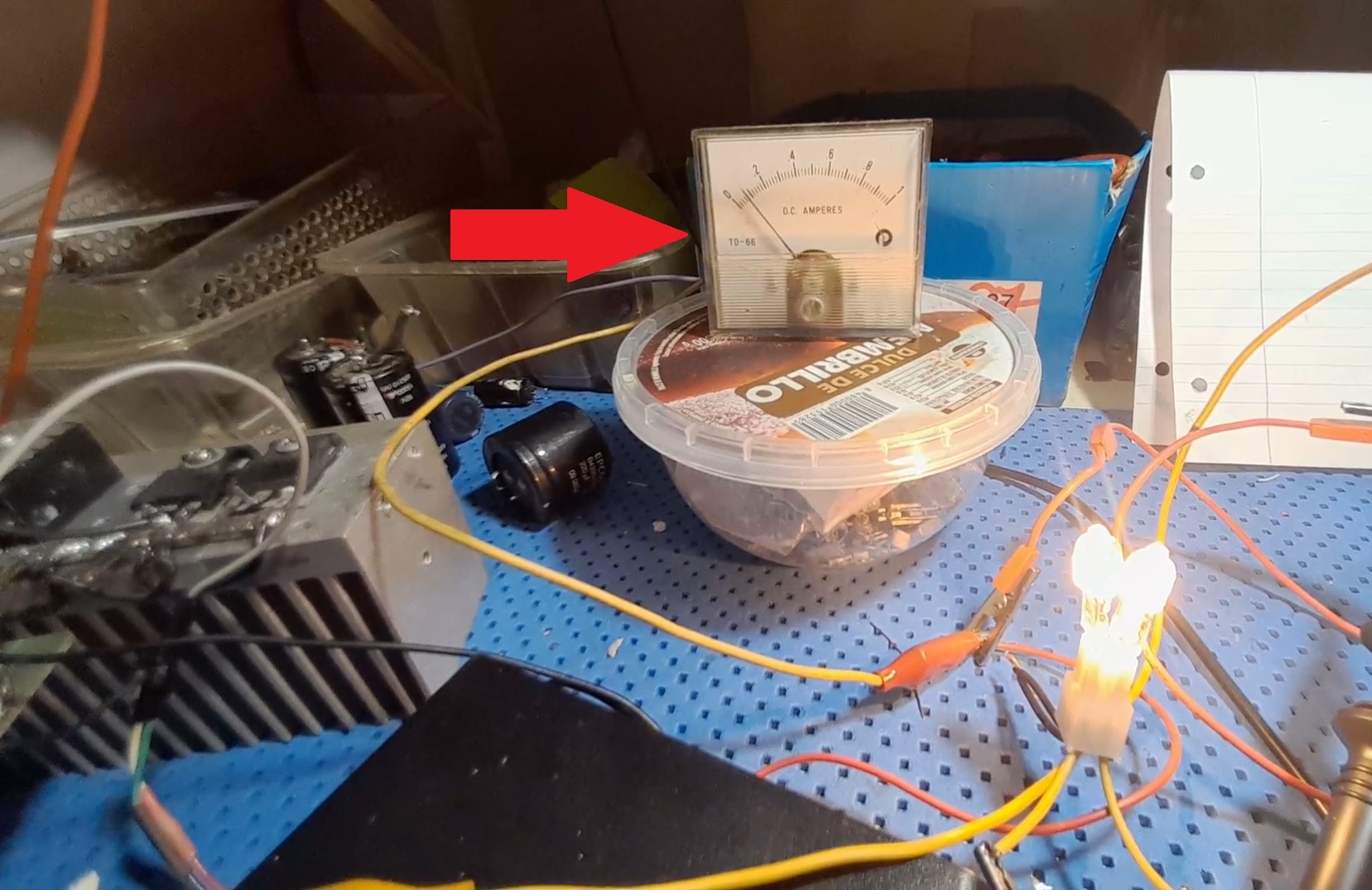
Did anyone paid attention to the analogue ampere meter showing the same input decreasing effect in Realco's successful ZPM replication (using a ferrite core !) here ?

Or Atti's successful ZPM replication (with and without grounding !) here ?

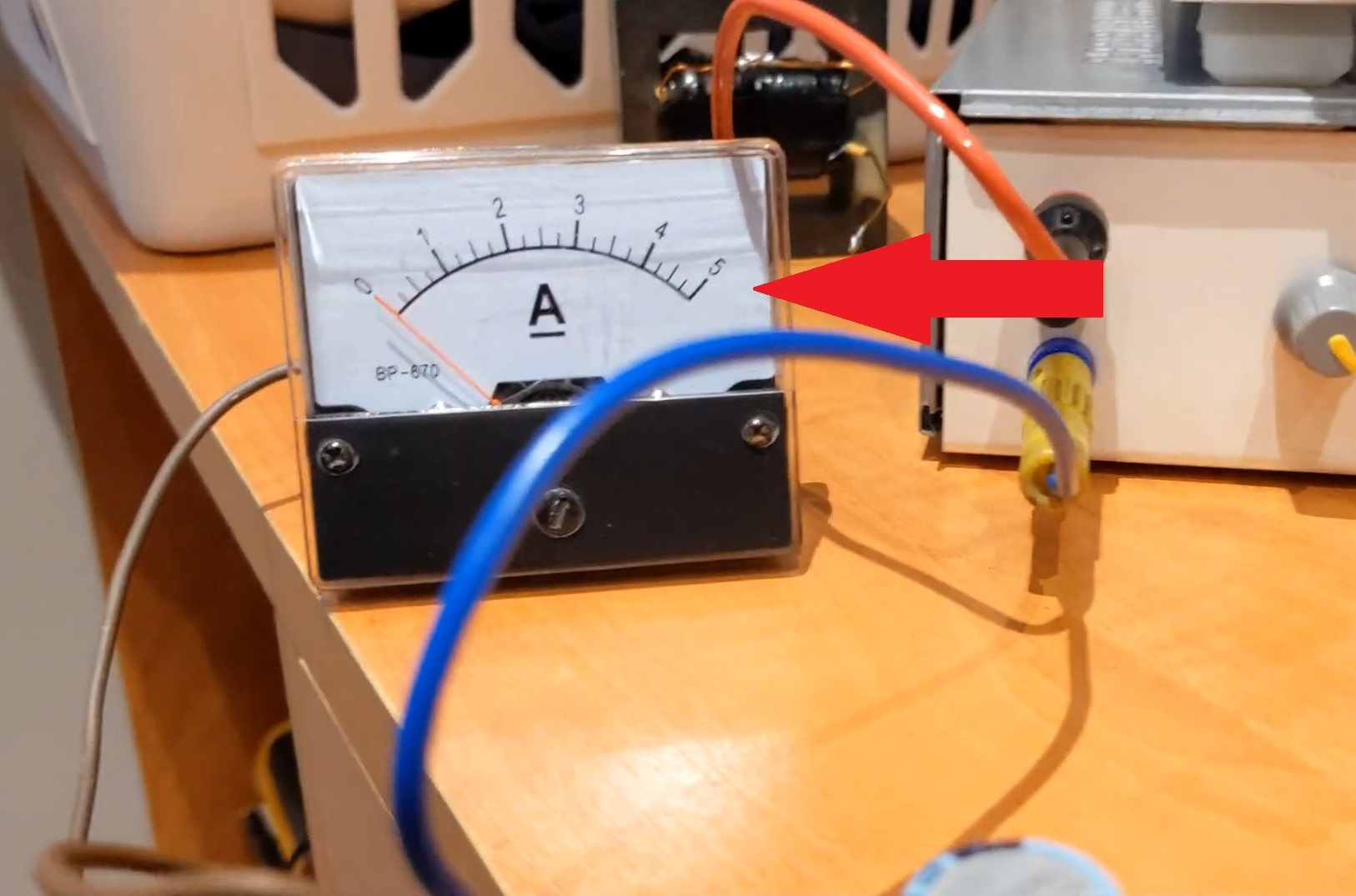
These secondary analogue ampere meters confirm the same input decreasing effect shown by the electronic displays.

There is the answer to your questions.

For me it was clarified a long time ago by that pretty advanced power meter (shown in the post fragment above) which confirmed the readings of my DC source:

The probability of ZPM messing the readings of two different devices (at the same ZPM frequency but with different components, different reading sensors, etc. ) but still the devices to show the same readings is the same as the probability to play at the lottery for the first time in life and win the big prize then playing for the second time and win the big prize again.

Technically and statistically the probability is 0.

By the way, I used those kind of power meters to measure the consumptions of the motors of my drones when I built and flown my own drones. The readings of those power meters proved to be always accurate no matter what kind of brushless motors I used.

Regards,

Fighter

"If you want to find the secrets of the universe, think in terms of energy, frequency and vibration."
Nikola Tesla
  • Liked by
  • YoElMiCrO
  • Inception
Atti posted this 27 June 2023

Same question editor asked, but can any of the successful replicators run their ZPM from a simple buck/boost converter, they usually have displays of V and A, sometimes Watts. I know they wouldn't be accurate, though very useful, and they are very cheap and will show if different power supplies would change the operation.


No. I tried and failed.  No effect of the current drawn decreasing.  Unfortunately, there is the coefficient of authority to be taken into account. 

Think about it. A world champion weightlifter can lift several times his own body weight. But can the weightlifter lift himself? Well, no.

I've tried a lot of power supplies and found that different lab power supplies are wired with different grounding. 
And that is the source of the confusion!
I have also tried with a battery and the interference also appears. 
In my opinion this is wrongly formulated by some researchers. This is not an electron pump. It's more like capacitive confinement by another pathway.  And it affects everything.  But it's still worth looking at the effect.


Atti.

AlteredUnity posted this 27 June 2023

Same question editor asked, but can any of the successful replicators run their ZPM from a simple buck/boost converter, they usually have displays of V and A, sometimes Watts. I know they wouldn't be accurate, though very useful, and they are very cheap and will show if different power supplies would change the operation.

  • Liked by
  • Inception
YoElMiCrO posted this 25 June 2023

Hello everyone.

@ Vasile.

You're right, the mistake was mine.
Hehehe, the one who got the wrong unit was me.
100/1000=10/100=0.1 meter.
dL/dT=Acceleration.
The tangent does not vary if the medium is homogenized and isotropic
as in the void, in that assumption the propagation is the one that
you calculated for the example I gave.

YoElMiCrO.

Vasile posted this 24 June 2023

Quoting:Jagau

Your mistake, you calculated the speed in tenths of meters per second, bring that back to meters per second, you will have the correct answer.

Jagau

What? You must be joking. What do you mean I calculated in tenths of meters per second? 100mm is 0.1m. 0.1m is not tenths of meters, it is 0.1 METRES. I don't get your logic.

Jagau posted this 23 June 2023

 The speed that Yoelmicro has calculated for you is correct and is in meters per second = 83.333 meters per second this speed does not change, only the time traveled can be shortened.

Your mistake, you calculated the speed in tenths of meters per second, bring that back to meters per second, you will have the correct answer.

Jagau

Vasile posted this 23 June 2023

Quoting:YoElMiCrO


It takes half the magnetic length to get to the secondary.

Alright, this seems logical.


In the example I gave, the speed you calculated the number is wrong, just that.
It is the same to say that 1/[(1000/100)*1.2*10-6]=83 333m/s.

What do you mean the number is wrong? You said " the magnetic wave took 120nS to travel 100mm...". 100mm = 0.1m and 120ns = 0.000'000'120s. Speed is distance/time(m/s) so we have 0.1/0.000'000'120=833'333.33 m/s. What is wrong in this calculation?

YoElMiCrO posted this 22 June 2023

Hello everyone.

@ Vasile.

If you look closely at one winding is facing the other, that is, at 180 degrees.
That means that when the primary is activated, the wavefront
magnetic reaches the secondary in the time shown by the oscilloscope.
Since the secondary is geometrically in front of the primary, this front only
It takes half the magnetic length to get to the secondary.
There is no more calculation than that!
In the example I gave, the speed you calculated the number is wrong, just that.
It is the same to say that 1/[(1000/100)*1.2*10-6]=83 333m/s.
That's the speed of propagation of the magnetic wave for that
Material/Geometry of the core in question.

I hope it helps.

YoElMiCrO.

Vasile posted this 22 June 2023

Quoting:YoElMiCrO


That means that the magnetic wave took 120nS to travel 100mm...

So that would imply that the speed of the wave in the core is 0.1m/0.00000012s=833'333.00 m/s.

Why did you use only 100mm for this type of calculation if the total lenght of the core is 200mm? Doesn't the wave travel all the cores lenght (200mm) before it induces something in the secondary? What is the reasoning for the halving?

Close