ZPM Related Questions

  • 1K Views
  • Last Post 27 June 2023
Fighter posted this 10 June 2023

In order to keep the ZPM replications threads clean I've created this thread when questions can be asked and discussion related to ZPM's functionality can continue.

We can discuss here about the standing waves on ZPM's output, the waves propagation in the core and any subjects not directly related to those ZPM replications.

Regards,

Fighter

"If you want to find the secrets of the universe, think in terms of energy, frequency and vibration."
Nikola Tesla
  • Liked by
  • Shadow_
  • Vasile
Order By: Standard | Newest | Votes
Fighter posted this 10 June 2023

In order to keep the ZPM replications threads clean I've created this thread when questions can be asked and discussion related to ZPM's functionality can continue.

We can discuss here about the standing waves on ZPM's output, the waves propagation in the core and any subjects not directly related to those ZPM replications.

Regards,

Fighter

"If you want to find the secrets of the universe, think in terms of energy, frequency and vibration."
Nikola Tesla
  • Liked by
  • Shadow_
  • Vasile
Vasile posted this 09 June 2023

Quoting:YoElMiCrO

I think Vasile is trying to generate a standing wave.
magnetic inside the material


Exactly. The thing that bothers me about electrical devices nowadays is that they do not take into account this propagation of the magnetic wave. Lets take for example the propagation of an electromagnetic wave in air which should have a speed of about 300000 km/s. For 50-60 Hz common grid wave, which is the standard in all countries in the world, we have a wave lenght (λ) of  v/f (following the formula v= λ*f, speed=lenght of the wave*frequency), which is somewhere beetween 5000 to 6000 km. That happens in the air, but what happens in a transformer? How to calculate the speed of the magnetic wave in a transformer? I never heard anyone in electrical engineering talk about this relating to transformer theory. They talk about saturation of the core, histerisys, current density, etc. Every wave has a tendency to behave in a prefered way (at resonance) in a specific construction so taking it into account is important.

I am asking all of these questions because they may have some relevance to why this device may work. Maybe for those that work, in the core we have reflection of the magnetic wave and thus a standing wave which has constructive interference going on and not a destructive one, meaning the incoming waves + the reflection add and not cancel.

Vasile posted this 05 June 2023

Quoting:Jagau

My replication of Figther's ZPM. As my two coils were already mounted on an AMCC320 I was able to replicate quickly.
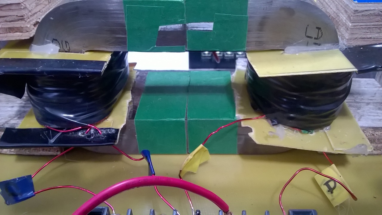
In the first image the 2 coils mounted on the AMCC320


In the second image when the power supply is turned on at 24 volts DC he sees an input power of 4.32 watts on 24 volts and 180 ma when my TL494 oscillator is supplied to both coils through an IGBT pulsed at 38.2% on the high side. Channel1 is IGBT pulse 


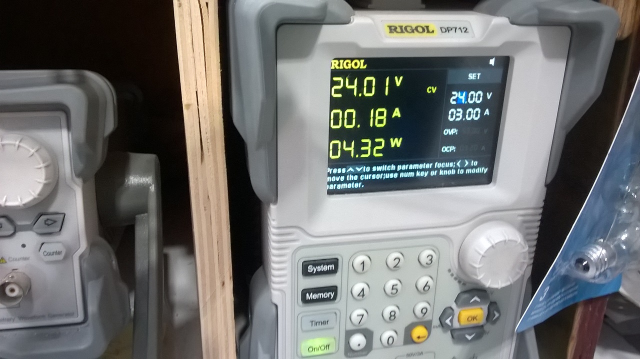
Image of the oscilloscope with the current probe on the PS

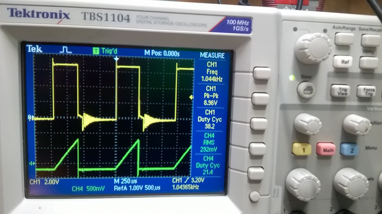
You can notice that the oscilloscope show on a my TEK current probe (green) 292mv =292 ma  (rectangular form) and 38.2% DTC

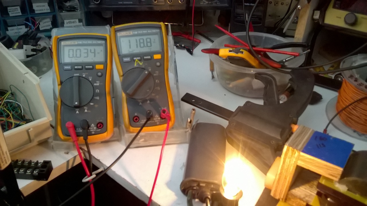
Last image the 118 volt 4 Watts lamp lit with 34 ma x118.8v = therefore 4.0392 watts of power produce at the output on a large capacitor and 4 diodes in parallel in order to produce an almost pure DC which can be read by the 2 DDMs

Calculation of input power in DCM mode with reactive component.

As indicated by the power supply we have an instantaneous pulse power of 4.32 watts, this is the instantaneous power not the average power over time.

V and I is what PS provided a DM as wrong lecture for input due to high frequency so to calc PIn we take well known formula for inductor.

Irms on scope is 0.292 Amp, DC voltage is 24volts

Pin= I*V*sqrt(Duty_Cycle)/sqrt(3)


Pin= 0.292 Amp x 24 Vdc x sqrt 0.382 / sqrt 3 = 2.533 watts

So for  Pout of 4.032 watts  i need only 2.533 watts at input, Still a pretty good COP
Jagau

Hey Jagau,

I followed your thread recently to understand your setup but I am confused of some things. Maybe you can clear them up or someone else. Lets look at the oscilloscope shot. The green waveform is the current of the PS and the yellow is what? the voltage waveform of the PS? I am asking this because your PS display is showing 24V but the scope is showing 8.96 Peak to Peak so at 38.2 Duty Cycle, the RMS voltage should be even lower than that. I think you understand my confusion, so again, what is the yellow waveform showing?

Thank you.

Jagau posted this 05 June 2023

Hi

This is only the pulse at the gate of IGBT coming from TL494 at  1044 hertz by square wave oscillator. The oscillator is powered by a 12 volt DC battery and you can see the linear rise of current in the green triangle shape, when the pulse is present. I hope that takes away your confusion.

Jagau

Jagau posted this 05 June 2023

In fact Vasile, if you look at the circuit provide by Fighter,  

these are two coils in phase opposition that are pulsed which produces a parametric resonance between these two coils. In my case, measured in phase opposition, I have a measured with an inductance meter 74 uh (microhenries) for total of the two coils in my case.

 As for the maximum current, it is determined by the duty cycle, the curve obtained is characteristic of this type of pulsed circuit. If you go over a certain limit, the fuses will burn.

Wikipedia shows a nice picture that represents the characteristics of a similar circuit well, you can see the same voltage characteristics versus current waveforms at on and off. Same i get for current in red triangle

Try this:   As I drew on the diagram, If you place a capacitor of 1uf not polarized in parallel with the lamp you will have a better luminosity of the lamp.


Jagau


bigmotherwhale posted this 07 June 2023

Hello 

What jagau has said is accurate, you just need the lenght of the core and a time. 

Kind regards

Vasile posted this 22 June 2023

Quoting:YoElMiCrO

Hello everyone.

@ Vasile

I think this image answers your question.
Anything let me know!

YoElMiCrO.

Thank you for the effort, but please clarify the following:

1)The formula that I am supposed to use for measuring the speed of the electromagnetic wave in the core is (1/2 le@td) ?

2) What is "le", what is "@" and what is "td"?

3) I am looking at your osciloscope diagram (the one in the middle). Let us suppose the power source has 12 V. On the moment of switch on the voltage drops because we have a load in the system (Inductance 1, L1). After some time it stabilises at 10V lets say, thats why we have the straight line. Looking on CH2, we notice that the waveform has a delay in appearing, meaning it does not appear instantly. So the first dot when calculating "td", is when the secondary voltage  waveform starts appearing?. Also what is the second dot? Is it the middle voltage moment of the rising voltage waveform in the secondary?

4)What is N1, N2 and B1? And also the formula N2/N1*B1

Regards.

Atti posted this 27 June 2023

Another example.
Here you can also see that the AMCC core is equipped with additional coils. 
In the first part you can see that the mains frequency is superimposed on the mains supply by the capacitors and the earthing. This must be taken into account. However, in this arrangement the current strength is almost unaffected.  There is only a change if I place the earthing at the point where the two coils meet!  Then you can measure the high voltage with the neon lamp. This is clearly shown in the second part. Here the test is carried out with a machine tool battery. At this setting, there is a very small decrease in the intensity of the current drawn and an increase in the voltage of the bulb. In this case, the high voltage appears everywhere.

So when using earthing ( either with battery or with some laborator power supplies), the capacitive way of closure is clearly visible. There are times when it causes an increase in current and times when it causes a decrease in current. 
As you can see this is shown when the neon light on the foot of the Mosfet Drain is on. 
I could not get this result without additional coils.


Vasile posted this 05 June 2023

Quoting:bigmotherwhale

Thanks Jagau, if this is not an LC phenomenon, then you have a propagation speed of around 8000 m/s in your core with a 32cm magnetic path, please correct me if im wrong maths isnt my strong point.  

could you try altering the capacity of one of the coils with a capacitor and measuring again or try pumping the core at this freqency?  

Hey bigmotherwhale,

I am curious how did you calculated the propagation speed to be 8000m/s and also the magnetic path of the core to be 32cm by simply knowing the frequency? I want to do some experiments and I need that information.

Thank you.

Vasile posted this 05 June 2023

Quoting:Jagau

Hi

This is only the pulse at the gate of IGBT coming from TL494 at  1044 hertz by square wave oscillator. The oscillator is powered by a 12 volt DC battery and you can see the linear rise of current in the green triangle shape, when the pulse is present. I hope that takes away your confusion.

Jagau

So only the green waveform is measuring the current from the PS. That green sawtooth waveform is pretty interesting especially at that low frequency. It shows that the maximum current in the circuit hasn't been reached else we would've seen a horinzontal line after some time of rise. That shows you have a high inductance in those coils.

Vasile posted this 06 June 2023

Thanks Jagau, if this is not an LC phenomenon, then you have a propagation speed of around 8000 m/s in your core with a 32cm magnetic path, please correct me if im wrong maths isnt my strong point.  

could you try altering the capacity of one of the coils with a capacitor and measuring again or try pumping the core at this freqency?  

I quoted bigmotherwhale in a few posts earlier about how he managed to deduce the speed of propagation thru the core to be 8000m/s and also the magnetic path of the core to be 32 cm, by only knowing the frequency, but he hasn't responded yet and I wanted to ask also the same question to everyone else on the forum maybe someone knows the answer. So, anybody know?

Close