Editor's ZPM replication

  • 4.3K Views
  • Last Post 29 June 2023
editor posted this 07 November 2022

Hello All!

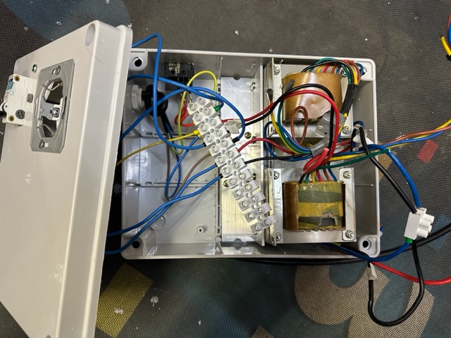
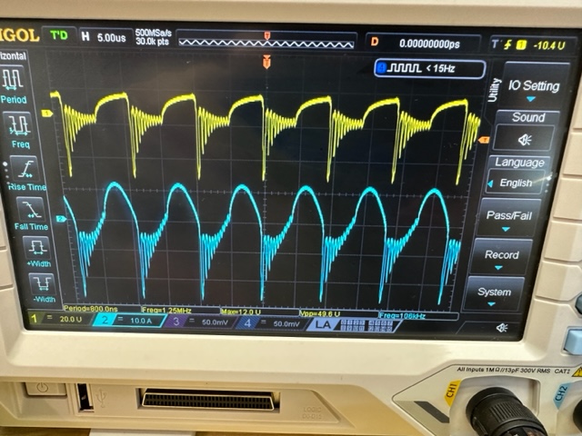
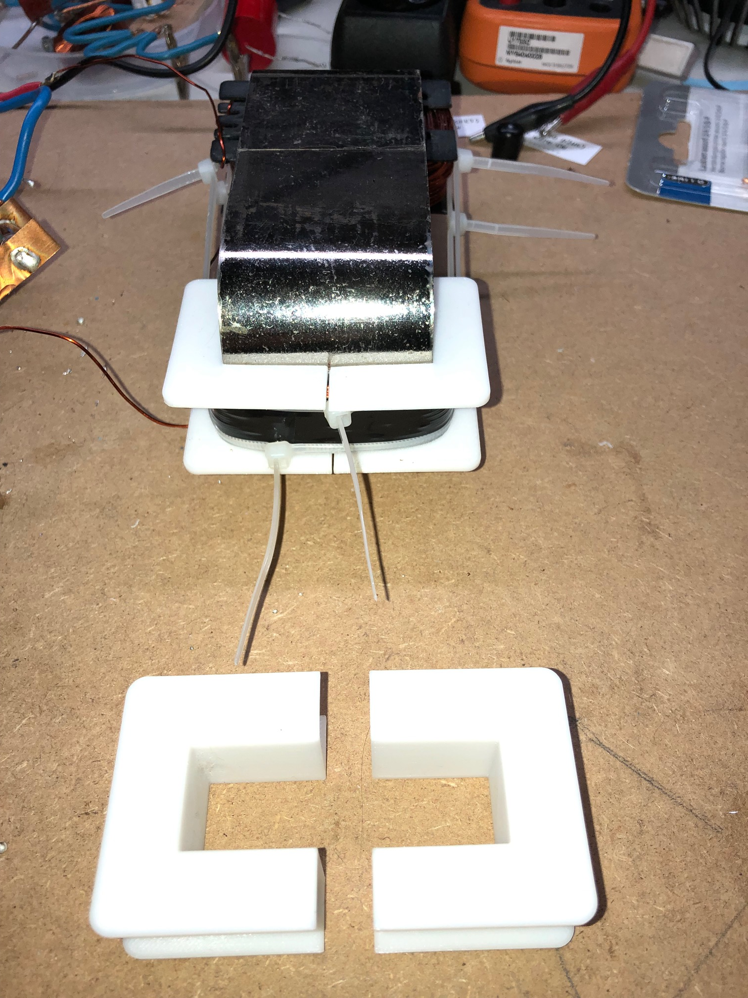
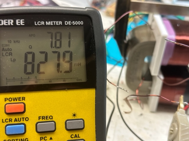
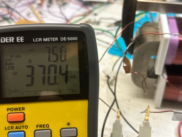
I was in touch with the Fighter and now I decide to show what is going on and to get some new ideas on how to get the signal that we all expect. Below is a quick video showing the simple setup. The coils are 1mm L1 cw 210T (370mH), L2 280T ( 828mH). 


The poles were tested with the phone app named Pole detector, works ok.

I have built some other coils too, with different turn numbers but the output was almost the same.

I have 2 different grounds to play with. I did use the regular power supply but my home appliances were not happy at all, so I decided to isolate everything.

For sure there are differences from Fighter setup, like the core, the position of the coils, the voltage, not sure about the ground.

the video:šŸ˜


bre


Fighter posted this 17 November 2022

Hi Editor,

Seeing the title from your link ("Switching Power Supply 28A") I remembered something.

Long time ago (maybe in 2014 ?..) when I bought equipment for starting replication of Tom Bearden's MEG I asked a friend which is very experienced in electronics: "I want to experiment with devices requiring pulses at high frequencies, what kind of power source do you reccomend ?"

And he sent me some links to a few DC power sources (including the one I bought) and insisted on the word "switching", he insisted it should be a switching power supply. He said "It will be more expensive and you'll notice it's more heavier than other power supplies but this is what I reccomend to you for high-frequency pulses".

So the switching power supplies are the only ones having the minus connected to the ground or it's just a coincidence and there are other kinds of non-switching power supplies which also have the minus connected to the ground ?

To be honest at this moment I don't know what's the difference between switching and non-switching power supplies, I never searched for this.

Regards,

Fighter

"If you want to find the secrets of the universe, think in terms of energy, frequency and vibration."
Nikola Tesla
Itsu posted this 17 November 2022


Fighter,

to my understanding, most if not all bigger Power Supplies are "switched" Power supplies nowadays as they do not need a bulky transformer (so they are lighter!).

Instead of a bulky 50/60Hz iron cored transformer to transform the 120 / 240V AC to lower AC and rectify to DC they directly rectify the 120 or 240V AC to DC, then have it switched (at several hundred kHz to several MHz) using a TL494 or so and MOSFETs and transfer it down to lower AC using a lighter ferrite or so transformer, see:

https://en.wikipedia.org/wiki/Switched-mode_power_supply

So a switched PS is lighter, not heavier, but more complex and more sensitive for generating EMI and thus more sensitive for pulsed feedback from its load IMO.

Perhaps your friend insisted it should be a NON switching PS.

As mentioned, all my PS here in the shack, switched or non-switched do NOT have the earth ground directly connected (fixed) to the minus lead.
With that i mean the PS's are all earth grounded but not connected to the minus lead.

Itsu


Fighter posted this 18 November 2022

Hi Itsu,

I'm sorry but I don't have the messages containing links I exchanged with my friend at that time but I remember well it's switching.

From the wikipedia link: "Unlike a linear power supply, the pass transistor of a switching-mode supply continually switches between low-dissipation, full-on and full-off states, and spends very little time in the high dissipation transitions, which minimizes wasted energy. A hypothetical ideal switched-mode power supply dissipates no power. Voltage regulation is achieved by varying the ratio of on-to-off time (also known as duty cycles)."

When I modify the voltage or the load is requiring more current I hear a specific "click" of (probably) an internal relay or something like this inside, this is how it worked from the beginning. I asked my friend at that time and he said "it's okay, this is how they work, mine is doing the same".

Unfortunately I don't know the manufacturer's site to check there but I found another clone, it's like mine just a bit different buttons on the panel, its manufacturer specify it's switching type, not linear:

Fighter

"If you want to find the secrets of the universe, think in terms of energy, frequency and vibration."
Nikola Tesla
editor posted this 19 November 2022

Hi,


Thanks to the effort to find the specs Fighter. Expecting to get one more inverter soon so I can

continue with the journey.

br, e

editor posted this 30 November 2022

Hi All!

Just some update, from the last time. I have to move again to my first lab, the temperatures are below zero so it is hard to experiment in those conditions.
I got some inverters and built an isolated transformer from 2 transformers from an old broken UPS. Works well for powering the scope, I also add a ground switch so I have all the options available. Still have to experiment a bit with different PS the best result was with the one minus connected to ground.
Today I played it with a ZPE with different loads but not getting the low power consumption like expected. The waveform is from the coils; the bulb is 50W low brightness and 1.7A 25V from accu. 


Have a great day or night, e

Fighter posted this 30 November 2022

That's exactly the ZPM waveform pattern, its signature.

I don't understand why you don't get the input decreasing effect...

Fighter

"If you want to find the secrets of the universe, think in terms of energy, frequency and vibration."
Nikola Tesla
editor posted this 30 November 2022

Hi Figter,


i don't get it too, but no warries many things are not clear to me in life.šŸ˜‚

I will continue with ZPE...


bre 

editor posted this 05 December 2022

Hi all!


One of the things that I like to try is also positioning of the coils. So I'm in a process of building the new formers

and a 3D printed vise for helping with winding the wire. (AMcc 320)

4pcs part, showing just 2


br, e


Itsu posted this 06 December 2022

Editor,

looking nice, could you tell somewhat more about the Vice?

I also have designed formers for my AMCC 200 core (on the far ends) as can be seen here:

The .stl files (left and right) are attached below (AMCC200.zip)

I also made some .stl files for the AMCC 320 core (left and right), also attached (AMCC320.zip), but be aware i have not tested them on a real core so there could be some mistakes / margin errors.

If needed i also have the Gcode files for a Prusa MK3 (Prusa slicer) PLA, no brim, full support.

Itsu  

Attached Files

editor posted this 06 December 2022

Hi Itsu, 

looking nice also, maybe I'm complicating too much. Well see. Tomorrow the Petg is arriving to get the better, stronger formers. Until now I was printing with PLA. I was also checking the RF performance for the PETG and It looks good from 0 to 30Mhz. Check the video:

About the vise, I was thinking how to wind the coils as quickly and simply with some control, maybe some day I have to with 10-20 coils in a hurry for family and friends so I have to have that in mind too.šŸ˜

It is still just an idea, but like you can see on the photos I took the vice from here:

https://www.thingiverse.com/thing:3421158

add a wooden platform to minimize the weight and add some M6 shaft for the drill.

The magnet is missing for counting the turns, with tha phone app called Turns Counter ( magnetic) IOS.

In this case it is very easy to use the phone to also count the turns. The drill will be operated by voice activation by a human operator ( family)šŸ¤£. Like you see I'm working on it, still have to do some small mods on the coil former, and print them. But this is it for the moment. Was just thinking today, how nice it would be to be able to participate in a weekend workshop in the center of EU with all of the active members here and finish this off, finaly. Just an idea.šŸ˜„


Close