
I transferred my thread on Ferrite at Work here to BeyondUnity.org
What we consider to be empty space is merely a manifestation of unawakened matter. N.T.
I transferred my thread on Ferrite at Work here to BeyondUnity.org
What we consider to be empty space is merely a manifestation of unawakened matter. N.T.
Hahaha!
L0stf0x, my freind, since I see you jumping in this, I know it will be a great journey! 😊
For you last experiment about the cap charger if you can draw a quick schematic it will help to replicate...
About the 12v version I already give it a try with the only 2 green led a have and as you can imagine I burned them... so I have ordered some more. Also a bigger transistor with a heat sink is needed. There are some variant to be found to switch this circuit to a higher voltage...
Anyway is great to play with it.
Take care everyone!
Rakarskiy (user name added by Fighter):
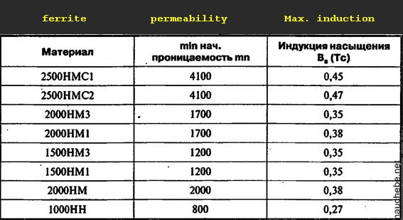
the relative initial permeability and saturation induction of the ferrite are different. Saturation is the maximum field limit that a material can create. Ferrite has a small size.
http://nauchebe.net/2014/10/konstruirovanie-impulsnyx-istochnikov-pitaniya-chast-5/
Lol Wistiti, you know me well ..yes I like simplicity in circuits and this one got my interest indeed 😉
Rakarskiy I use "Dumbbell winding" at the last circuit. But you are right about winding resistance!, with fewer revolutions! I will check it as you suggest!
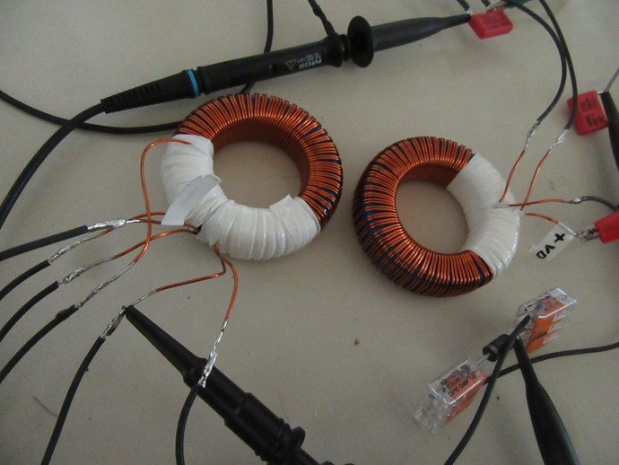
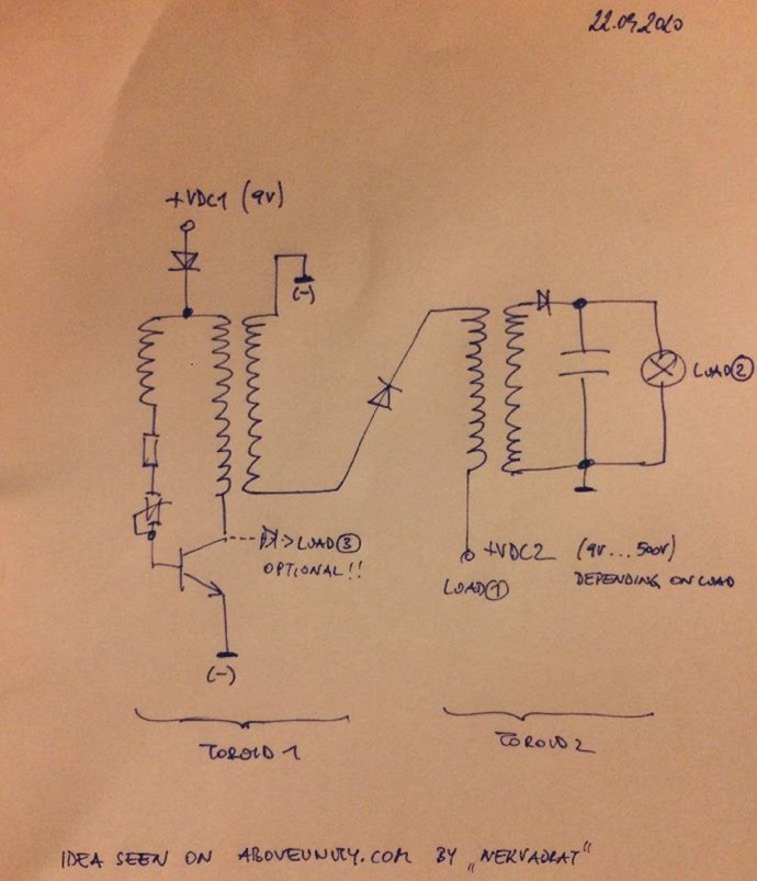
Wistiti here is the Cap charging circuit as I did it. Coils winded as shown. I hope its correct 🙂
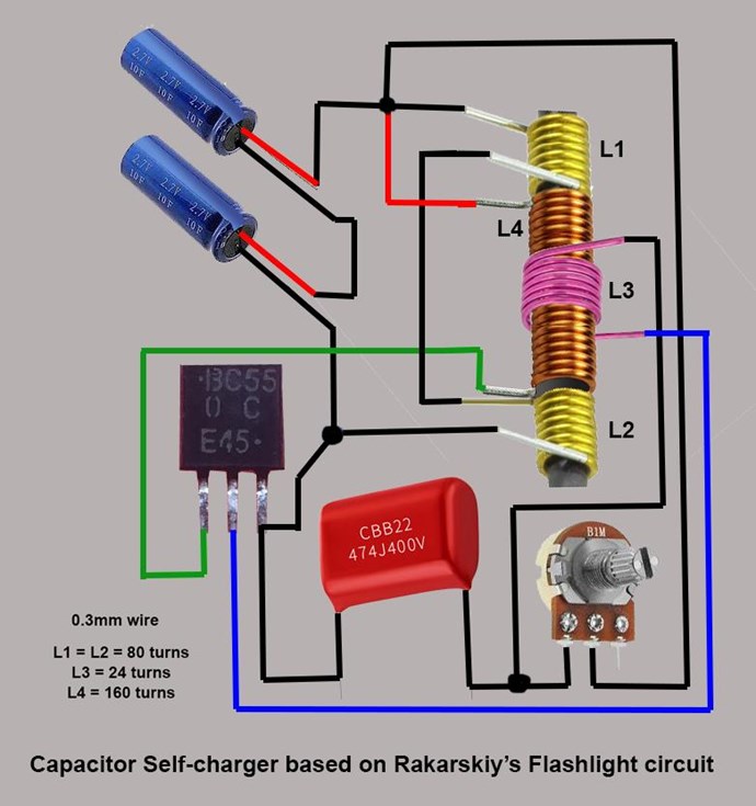
*The turns need change according to Rakarskiy's suggestions for better efficiency.
Hey Guys,
Just a heads up, those Caps are Super Caps: 2.7V 10F and 5.4V - 5F, they are super Caps.
Under certain conditions they will be ok, but give them a charge from a battery, they could charge enough to run for months by them selves. Something to beware of.
Hey L0stf0x, thank you my friend. I will try it.
UndisclosedMember you are right about the cap but if it charge there are no doubts!
Rakarskiy, thank you for being with us!
Rakarskiy (user name added by Fighter):
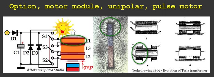
This combination is very interesting, the first such placement of windings was performed by Nikola Tesla. All in the concentration of magnetic lines of force at the poles. You should get acquainted with another project on the Internet. A coil for a pulsed unipolar/ bi-monopolar motor was also developed at the time. Everything is based on the topology of correct operation with the magnetic field of the core. With respect.
https://commons.wikimedia.org/wiki/File:Tesla_drawing_1899_-_Evolution_of_Tesla_transformer.png
https://rakatskiy.blogspot.com/2017/12/generator-of-energy-on-nonlinear.htm
thought about this circuit for days now. think the idea behind is brillant..
because the switching is done on the lowside there is a massive pulse in L1. L2 gets this energy (with some gain in voltage) and transfers it into the second 'stage' where another gain can be achieved - but this time we can gain some more current.
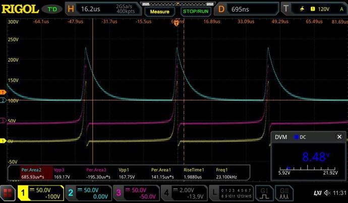
Ch1: Input pulse (from Transistor)
Ch3: This is L2
Ch2: This is the second toroid - we have 2 points for extracting energy! Ch2 is measured under load (25W resistive load)
Ch4 (DVM): superCap charging point.
this circuit can be used for charging batteries with little voltage (it acts like a boost-converter) for example. this is very useful i think. and maybe there is aboveunity somewhere.
the energy consumption from DC source (supercap) is under 6Watts.
thank you guys!
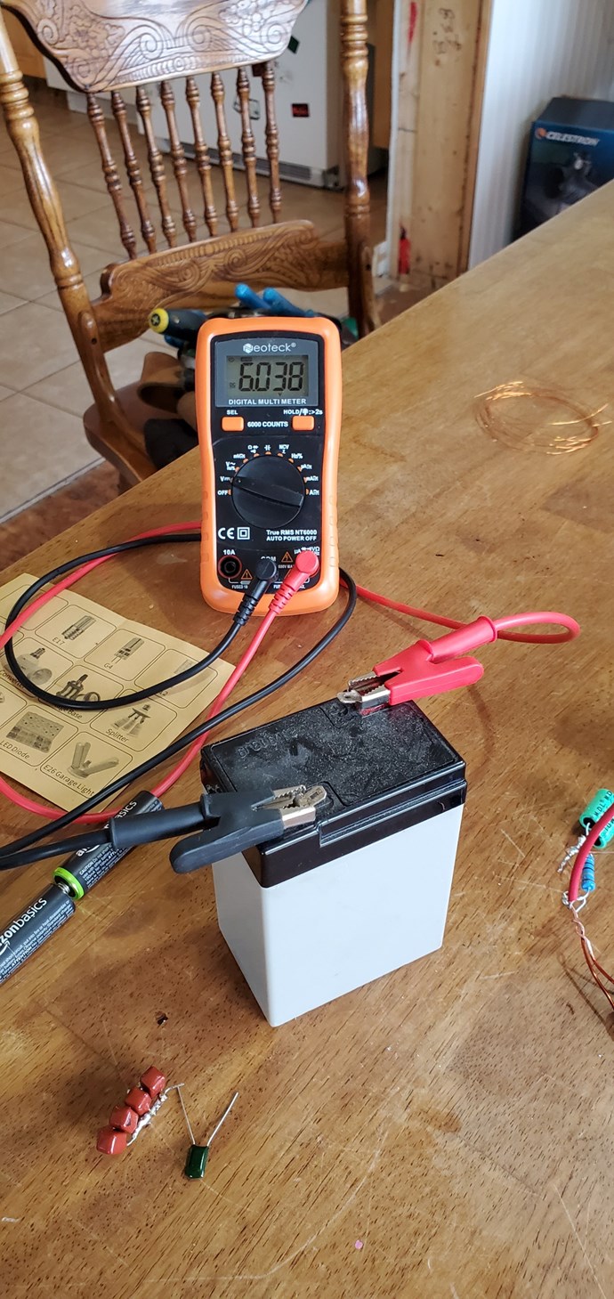
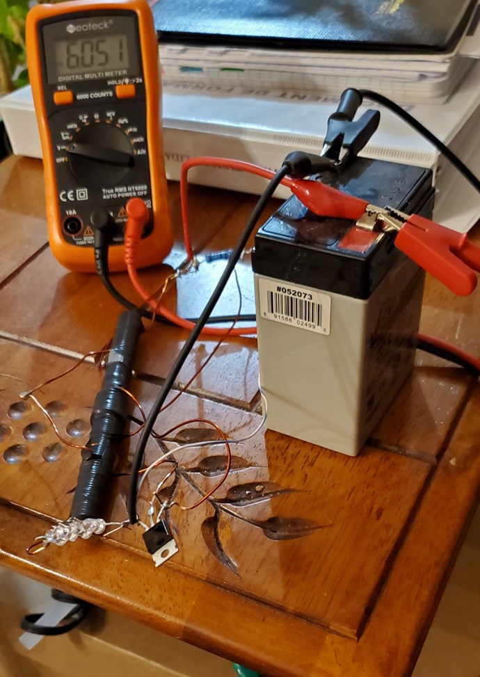
Hi team! Nice work Baerndorfer! I have some little time this weekend to experiment a bit. I try the last circuit sketch by L0stf0x for the super cap. I don't know why... but again I have to reverse the coil on the base of the transistor. It is an interesting way to use POC. I will try this in other experiment to see the effect compared the way I usually connect them. Anyway I have not try on super cap but it works on 6 v lead acid battery! Thanks you and will love to see others experiment!
Wistiti! great to see that works for you too my friend!! 🙂
I want to add few points about the original circuit posted by Jagau, that I think will help the replicators to adjust it easier.
First of all do not underestimate the small cup C2 that is shorting the one loop coil L6. As I see it, the L6 purpose is to synchronize (tune) the two ferrites with the main frequency of the circuit. The other coils that suppose to be equal, must be equal, and the length of their leads should also be equal length and diameter of course. Or you can use an induction meter to trim them equal accordingly. If the circuit oscillates ok, the LED1 will light up anyway. But to get to the magic point you will have to light up the LED2 as well (Maybe will not light up with the same brightness as the LED1) but what you need to make sure is that they oscillate with the same rate without interruptions or delays from LED2 following LED1. This may not happen if the capacitor C2 is wrong value. But maybe you are lucky enough and the closed loop without any capacitor will much. Or you can try different width wires or by adding more loops at L6 and checking loop by loop where you get the wanted result. C1 and potentiometer are there to give the desired range of frequency only. All the game is played at the correct (balanced) coils and C2. Again these are my observations and conclusions from testing it and I maybe wrong.
I just got a shock tonight, while checking how the thing was running, I measured the amp draw again and it was not 50ma as I thought, it was .5 ma! Is no wonder that this thing will run long time on a D cell NiMh. And to boot, burning out led's too. Sadly tho, it still is not charging as it should. Will follow LostFox's idea and rebuild it again with his things in mind. Seven is the lucky number, right?
😉 thay

No one online at the moment


