Halfbridge circuit observation

  • 608 Views
  • Last Post 30 November 2023
baerndorfer posted this 14 November 2023

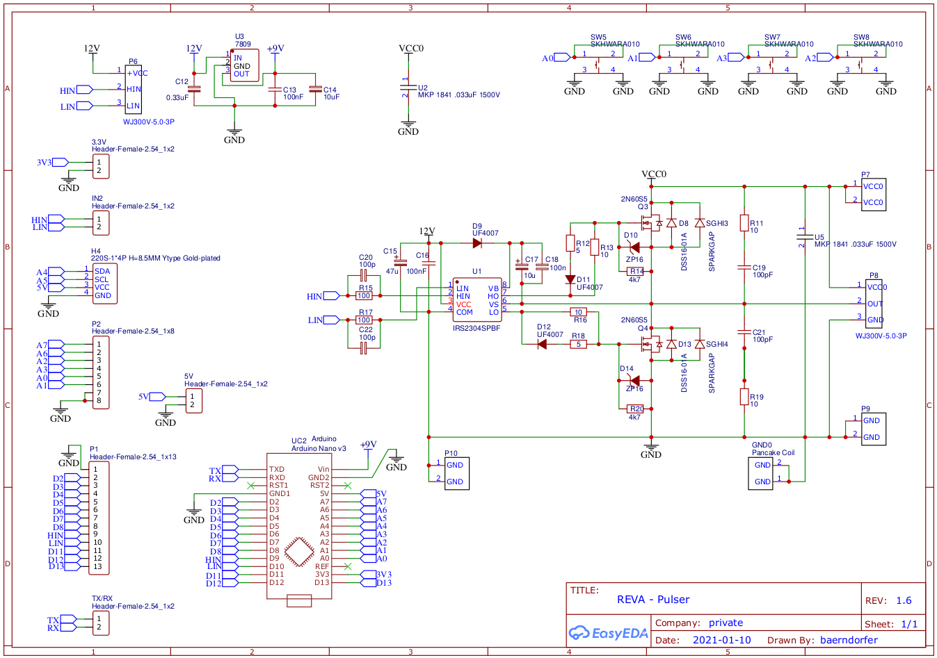
some time ago i build a halfbridge for doing experiments. the circuit looks like this,,,

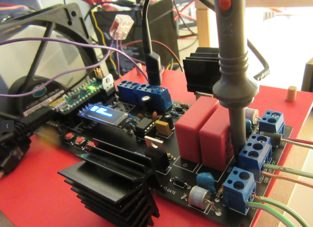
i managed to design a scetch for arduino where i can adjust frequency and duty-cycle. the thing looks like this...

i use infineon IRS2304 as gate-driver IC.

when i look into datasheet i can find information about amount of time which is taken by IC to switch ON or OFF.

so it took between 70 and 120ns for IC to turn ON

and it took between 35 and 60ns to turn OFF

---

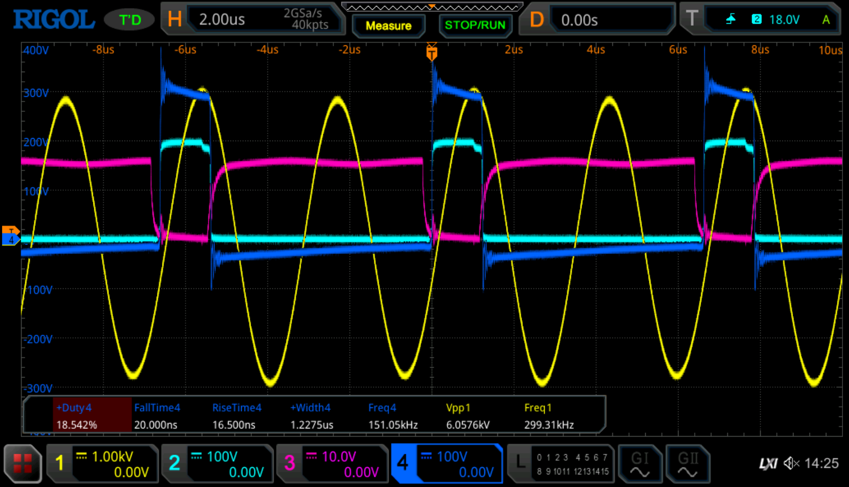
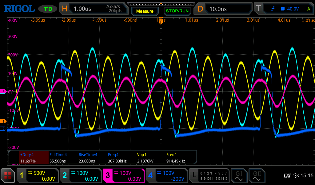
today i did some experiments where i use this halfbridge and on oscilloscope screen you can find output from halfbridge on CH4 under load.


now as we can see, the RiseTime and FallTime of the output from halfbridge is incredibly fast compared to the data given by datasheet for gate-driver. 

on CH2 we can see the Gate-Signal from highside-FET and CH3 represents Gate-signal from lowside-FET.

CH1 is Resonance-Signal from secondary coil-system which should be not relevant for the input situation.

at the moment i cannot understand, why the output signal has such sharp edges. 

hopy some electronic-experts can help me understand better.

regards

B

Attached Files

Fighter posted this 25 November 2023

My guess is that capacitor gets hot because it can't handle the high frequency. High-ESR.

I don't know if there are available 16KV capacitors but with low-ESR, that should solve the heating problem in my opinion.

Considering what we see in the thermal image, you should check it. If it reached that temperature I think it's already damaged. I doubt it's still functioning as in its specifications.

About the driver, I'm sorry, the image makes me think at the components I destroyed during my different experiments and especially during ZPM's development. Unavoidable losses, that's a part of the costs of our research...

Regards,

Fighter

"If you want to find the secrets of the universe, think in terms of energy, frequency and vibration."
Nikola Tesla
baerndorfer posted this 30 November 2023

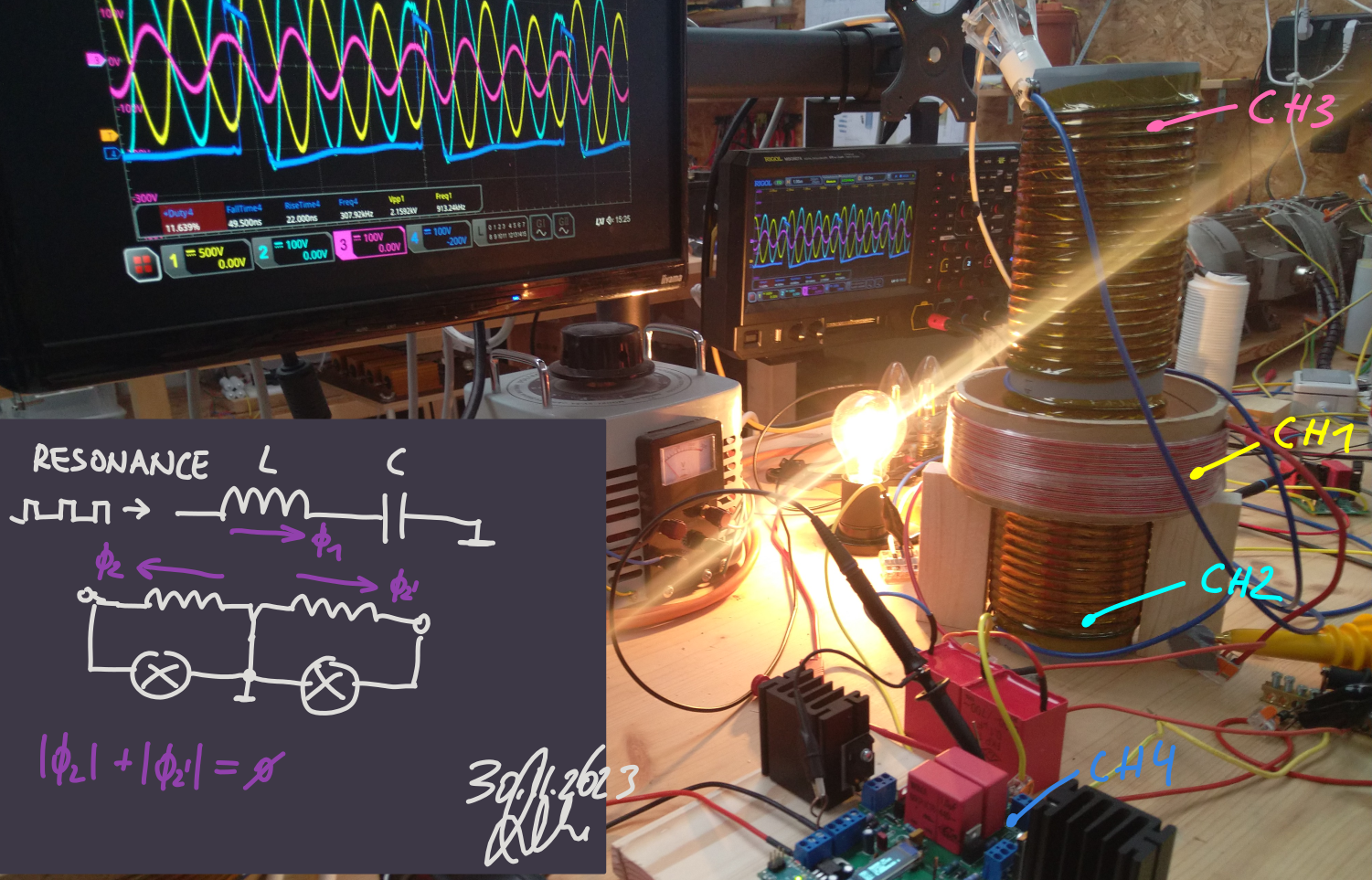
to understand more i wound a new secondary coil. the difference to first one is, that i gave the windings more room. don smith said, that we can increase Q-factor by adding more distance between each windings.

i use asymetrical load (100W and 60W light bulp) and connect the center tap to GND.

CH1: primary coil Resonance / CH2: secondaryCoil(bottom) / CH3: secondaryCoil(top)

compared to old secondary coil, this new one is more powerfull in terms of output. 

regards

B


Jagau posted this 30 November 2023

I think the power analyzer will give you great insight.
Nice work Bearndorfer

Jagau

Close