
I transferred my thread on Non Linear Resonance here to BeyondUnity.org
What we consider to be empty space is merely a manifestation of unawakened matter. N.T.
I transferred my thread on Non Linear Resonance here to BeyondUnity.org
What we consider to be empty space is merely a manifestation of unawakened matter. N.T.
Hi Jagau.
Thank you for your reply.
I'm looking for correlations in different machines,different implementations. For me, very often it doesn't even matter if the presented arrangement gives additional energy.
I am looking for the effect. Why? Because for me, this transformer machine is the etalon.
https://brevets-patents.ic.gc.ca/opic-cipo/cpd/eng/patent/2172240/summary.html
This machine has been seen by several people. Several people have tried to reproduce it without success. I'm one of them. If you think about it, there's a similarity.
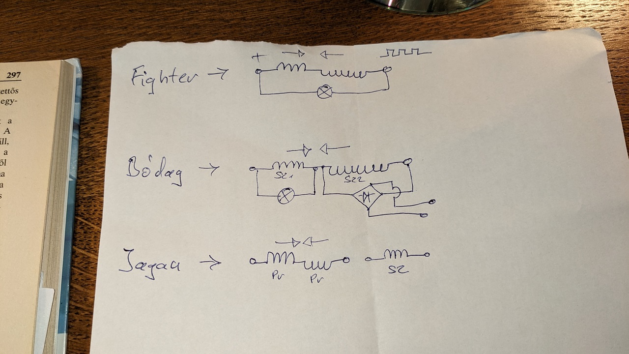
Looking at your layout, I see the same thing as Fighter's layout.
(and elsewhere)
Why is the geometric layout important?
It makes a difference whether I wind the wires in a trifilar winding or on top of each other.
Think about it.
In your layout, the coils are on top of each other. So the lengths of the wires are not the same.
First row is 100 threads. L1. As the cross section (AxB) increases, the diameter increases. So logically the next number of runs (L2) is longer than the previous number of runs.
So L1 and L2 have the same number of threads per revolution, but not the same in centimetres!
If I increase the frequency then the inductance increases! Think about it.
It is in opposite magnetic field.
However, it does not have the same effect on the primary energy source.
And that's the point.
In my opinion, this should be the basis of any machine.So every observation is very important.
(Addendum,explanation to the interpretation of the post.
Some information about Árpád Bóday's machine. Unfortunately, the inventor was extremely secretive.
I apologize to everyone.The reason I didn't fully address the Jagau non-linear resonance post is because I was not thinking closely about it.
Please refrain from inappropriate and out of place thoughts.)
Thank you for your patience.
Atti.
Hello Atti
Thanks for the link, I'll look into that.
It's as you say for the moment you concentrate on the effect, the balance will come and above all we can do much better, I will show in due time.
When you wind 3 coils as I did, in a potcore, I have already demonstrated with an inductance meter that the inductance is almost the same for each coil, even if the cables are a little longer compared to each other. to the other. Make the observation you will see.
Despite the similarities of the 3 systems that you demonstrated, their assembly and their load are different, which causes different results.
For my system there are three coils and the load is on one side of the third coil which is an open system. The environment can contribute in this type of arrangement to increase the output.
Unlike a closed system which gives a little less output than input minus losses.
I appreciate your comments, it’s very good.
Jagau
What we consider to be empty space is merely a manifestation of unawakened matter. N.T.
Hi Jagau.
Of course you are right. Your experiment is an open system. That's why I said I didn't want to mislead you about the nonlinear system thread. Once again, I apologize to everyone.But while we're at it, let me show you that there is indeed a high voltage in such a system.
As you can see in the video. N27 ferrite core. 3x 100 thread count.
The oscilloscope measurement is on the top thread count. L3 (10x measurement and cannot be measured completely because of the high voltage. The neon light is on!)
The bottom two are the two opposite coils. L1-L2.
As the diameter of the coil increases due to the increase in threading, the length of the coil in centimetres logically increases. Even though the thread count is the same (I measured it exactly! )
At this frequency, even this tiny difference is considered inductance. But the difference is only a few centimetres.
So that's why I said that it is similar to the ideas in the drawings given.
But again.I understand that your system is open. And there is logic in that.
Thank you for your patience.
Atti.
Excellent demonstration Atti
You have reproduced exactly the right experiment, yes if the input power is of 0.672 watt it will give a reading more difficult to read, in voltage, on the oscilloscope. This is why I used the output of a function generator with only 0.222 watt to demonstrate.
More experimentation try that:
Take two fast diodes in AV plug setup and connected them to the output, on one side of the L3
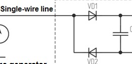
you can read the RMS voltage on a DDM, loaded this voltage into a capacitor (lower than 10 uf, non electrolytic if possible) and a 1K resistor in parallel on the capacitor and calculated the output power.
You are in advance, Bravo
Jagau
What we consider to be empty space is merely a manifestation of unawakened matter. N.T.
We can also make an arrangement with my small Self Resonat Oscillator SRO
It works wonderfully with this arrangement.
Jagau
What we consider to be empty space is merely a manifestation of unawakened matter. N.T.
Hello Atti
Have you tried an AV plug on a single wire at the output and measured the voltage?
Jagau
What we consider to be empty space is merely a manifestation of unawakened matter. N.T.
Hi Jagau.
Yes, I tried it. The single wire system (AV plug) doesn't work so well for me. As soon as I put the load on the diode/capacitor output the voltage drops. I used values of 100ohm, 1K,10K, for the load. The voltage drops below one volt. Connecting a ground to the other end of the output wire does not improve the output voltage magnitude.
Interesting fact.
If I try to apply a load to the output wires in a conventional way, at some point the primary current drawn from the power supply drops. This load is a small light bulb. However, it does not light up.
Only when I use a spark plug (so it arcs).
I think that is when capacitive reactance compensation takes place. There is current, no voltage. Or correction.
But even so, the energy level is weak.
For now.
Atti.
Yes, it’s completely normal Atti, you should not place a charge immediately at output. You must charge the NP capacitor before discharging it into a small 120volts lamp, after about 3 seconds you should have between 350 and 500vdc depending on the capacity of your capacitor,i used 7UF NPcap, and we calculate the power in volts/second like yoelmicro suggest it.
There are different ways to do a capacitor dump, the simplest is manually and the other is with a comparator LM339. If you want a model I can show it to you here.
For example in this comparator you can change the reference voltage with a R2 100k variable to adjust the discharge voltage required in your circuit or use a mosfet at the output.
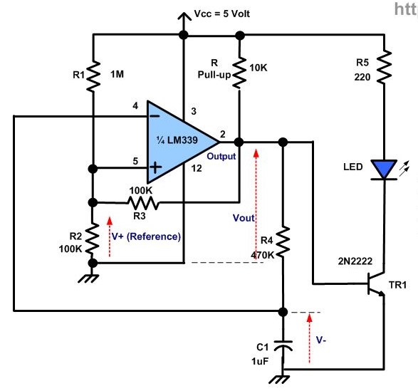
more delails here
https://www.ermicro.com/blog/?p=1578
When you have mastered this part, I will tell you how to double your output power, good experimentation Atti
Jagau
What we consider to be empty space is merely a manifestation of unawakened matter. N.T.
How to make power calculation with capacitor, so the energy expended to stored joules in a capacitor.
quoting Yoelmicro
You're right, power is energy per frequency (Ef) or energy between time (E / t)
as well as voltage per DC current.So the energy expended to produce 550V in a 7uF capacitor is ...
EIt = 5 * 0.019 * 2.5 = 0.2375 joules.and Yoelmicro gave here an exemple how to calculate:
Let's calculate the energy stored in the capacitor ...
E = Vc ^ 2C / 2 = (550 ^ 2 * 7 * 10 ^ -6) / 2 = 1.05875 joules.The energy efficiency is Eout / Ein = 1.05875 / 0.2375 = 4.4579.
Corroborating your calculations.
So i think it will help lot of us to get correct calculation about capacitor calculation and joules stored.
Jagau
What we consider to be empty space is merely a manifestation of unawakened matter. N.T.
Hello everyone.
This is just a manual test. There is no timing circuit.
A sudden discharge of energy stored in the capacitor can cause a problem in an improperly selected mosfet. Or a switching element.
Think about it. The energy stored in the capacitor.
If 1 J of work is done in 1 s, you get 1 W of power.
But if you do 1 J of work in 1 ms, you get 1 kW of power.
And if 1 J of work is done in 1 µs, you get 1 MW of power.
And so on.
This reminds me of thyristor ignition.
Given the right parameters, using spark gap is also interesting for non-inductive primary drive. As I mentioned above.
Instead of a timing circuit, another usable variant. In my opinion.
Atti.

No one online at the moment

