
I transferred my thread on Non Linear Resonance here to BeyondUnity.org
What we consider to be empty space is merely a manifestation of unawakened matter. N.T.
I transferred my thread on Non Linear Resonance here to BeyondUnity.org
What we consider to be empty space is merely a manifestation of unawakened matter. N.T.
Thanks for the encouragement but i dont have significant discovery to contribute. Here with tesla coils i was trying to understand Vasmus device. I have not kept any of my circuits. I reused all components in new experiments until they burned or fell apart. If I find anything worth sharing in the future, I will share it! Kind regards, Sandy
Hi Sandy.
I have not kept any of my circuits. I reused all components in new experiments until they burned or fell apart.
I used to be the same way. Don't make that mistake because you won't be able to come back later to recall the details.
If you're serious, of course.
Atti.
Hello guys, I have been doing some experiments with one wire transfer with regards to resonance. I can recommend the Resonant Induction Coupler Kit from Rick Friedrich, if you want to get hands on experience with one wire transfer. The kit comes with a book. It is easier to get the kit, but as most people here are not afraid to build something, you could find the book that comes with the kit, for example on Anna's archive, and then do the experiments yourself. I did that and it worked quite well for me.
What I find as the main advantage of one wire transfer is that I can connect two circuits with one wire without both of them getting out of tune.
Hy Kloakito
Indeed the advantage of a single-wire open system is that it can be loaded without affecting the source.
Rick Friedrich is one of my favorites, he is a great humanist with a passion for research.
Jagau
What we consider to be empty space is merely a manifestation of unawakened matter. N.T.
I love this thread. Thanks to all here. I'm trying to follow along, circumvent my own shortcomings and build too.
I found this interesting as well.
https://realstrannik.com/forum/delamorto/1392-usilitel-toka?start=0
Answer to HansKammler
There are two simple ways to make it work:
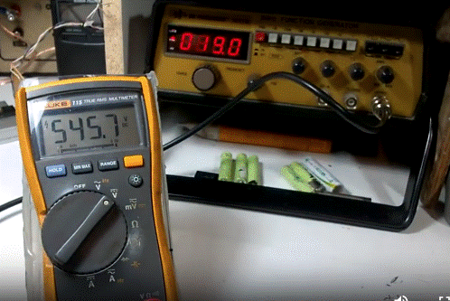
First one is with your function generator set to about 20 kHz if you have about 80 mH with each coil, about 40 to 60 times what you inject into the circuit, watch your finger near 545 volts DC with a F.G.
dangerous voltage here for you, do not touch capacitor it is at your risk.
see here
and the other is with my Self Resonant Oscillator SRO, like this with two AA batteries, Adjust pot R2 to get the desired output on both AV plugs. It will find the right resonant frequency automatically for you if you follow the schematic correctly.
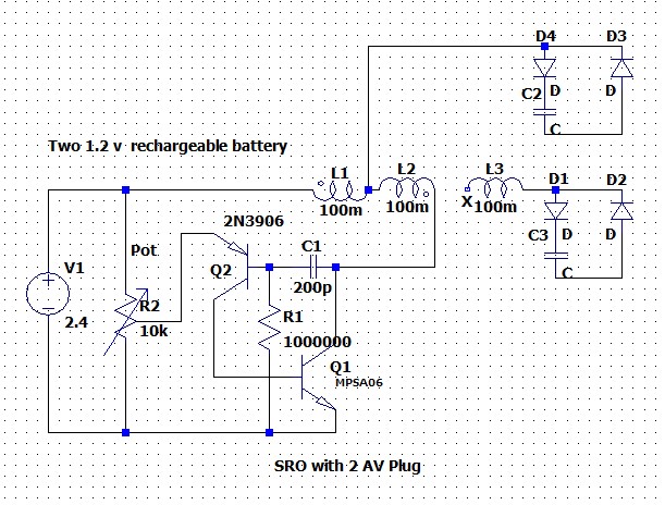
On each cap up to 150 VDC
Jagau
What we consider to be empty space is merely a manifestation of unawakened matter. N.T.
wow that sounds great ! you did it well.
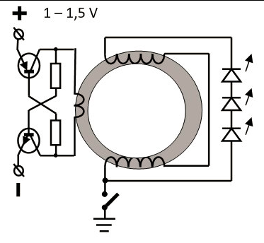
SRO:
advanced Joulethief with better efficiency. Did you get on avramenko the same power as on the other cap in the same time ?
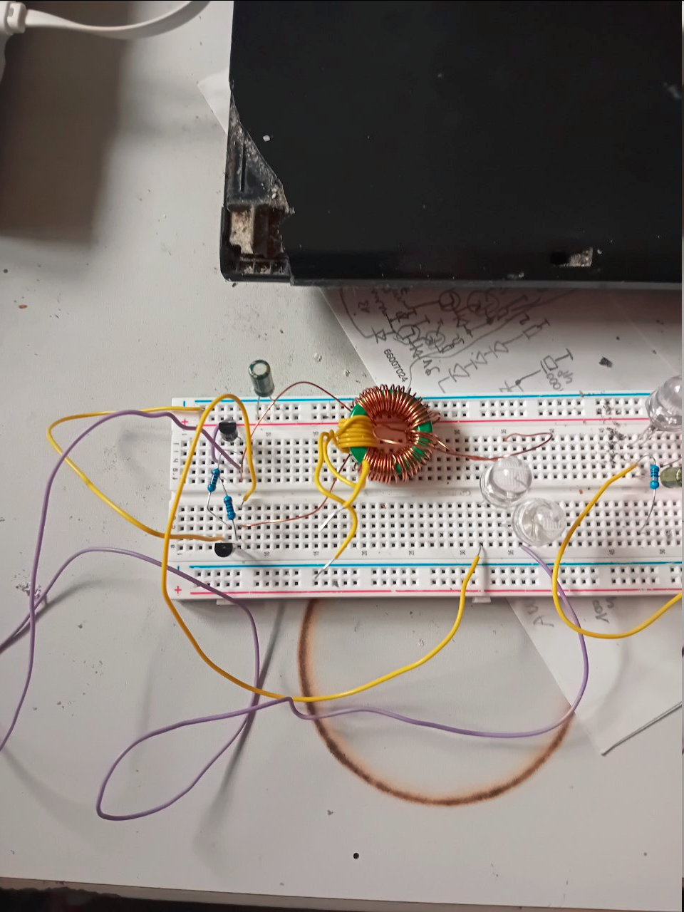
I use a similar schematic at the moment. Autotune too. at the moment with BC548 BC558 at 480 Khz with small ferite Ring a 30mm.
1.5 Vin , 16 V out and two 1W Bigleds shine brightly.
schematic:
The earth pump didnt work . I think i need 100x more turns on the coil for the effect and this has to be evaluated later.
for your FG:
I am correctly when I say: 10Vpp on 50 Ohms on the FG is:
P=I^2 x R = 0.4 x 50 = 20 Watt power from FG in your setup to create imense Volts on CAP?
Resistors on schematic 1K.
at first start frequency was changing from 10K to 180Khz and then stabilized on 480Khz +- 10%
no clue why. maybe battery voltage fluctuations.
the photo is a little bit different since I reconnect the ringcoils to test the Romanian ZPE which worked great.
This is why the yellow wire coil is not used because I have RZPE config.
i wait for elec. parts then I continue my tests.
Its great that I found your Website !
I also change your Harvester micro generator with this. I use a single Transistor to shoot the power from the 10uF CAP to the LEDs.. I did this with the transistor in reverse Mode. Here he acts as an avalanche Mode. When the CAP has more than 15.8 Volts the Transistor dumps it to the LED. Maybe you can use this too ? Watch polarity of circuit !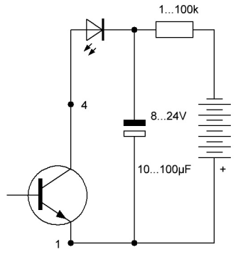
for your FG:
I am correctly when I say: 10Vpp on 50 Ohms on the FG is:
P=I^2 x R = 0.4 x 50 = 20 Watt power from FG in your setup to create imense Volts on CAP?
No it's not correct, to calculate the current, do not take the P/P values, take the RMS values please and impedance not resistance.
For an FG it is the frequency and the impedance, therefore the type of inductive circuit used, which is important.
Sorry but the maximum that a F.G. can provide is 1 watt in the best case of impedance matching, and this is a max, check in the specs of your FG
It is not the same calculation for inductive circuits compare to a resitive circuit.
Jagau
What we consider to be empty space is merely a manifestation of unawakened matter. N.T.

No one online at the moment


