Romanian ZPM (Zero Point Module) - Enhancements Stage

  • 4.1K Views
  • Last Post 28 November 2023
Fighter posted this 13 February 2023

This is the second imported thread (from the old aboveunity site) about my ZPM:


For references I will keep the original posting date for every imported post.

Note: This thread is public, everyone can see it, even the visitors which are not members here.

For the posts made by former aboveunity members which are not members on our site I'll use a member placeholder named UndisclosedMember.

Regards,

Fighter

"If you want to find the secrets of the universe, think in terms of energy, frequency and vibration."
Nikola Tesla
Fighter posted this 08 March 2020

@Vidura, I think this is what you remember: I ran a test with a single 12V/5W light bulb with the oscilloscope's probe put directly on ZPM coils and there is 254Vpp:

And here is the same configuration but the oscilloscope's probe is connected now on light bulb's pins and there is 242Vpp:

Comparing the two measurements as you can see there is a 12Vpp voltage drop on the same wire between ZPM's coils and light bulb's pins.

This voltage drop increases significantly when there are bigger loads like one or two 12V/55W light bulbs.

I consider the presence of different voltages on the same wire in different points of the wire the proof of the presence of standing waves on ZPM's output. The physics I learned in school told me this phenomenon shouldn't be possible (except when the wire is very very long) but still here it is present in a very short wire.

"If you want to find the secrets of the universe, think in terms of energy, frequency and vibration."
Nikola Tesla
Fighter posted this 08 March 2020

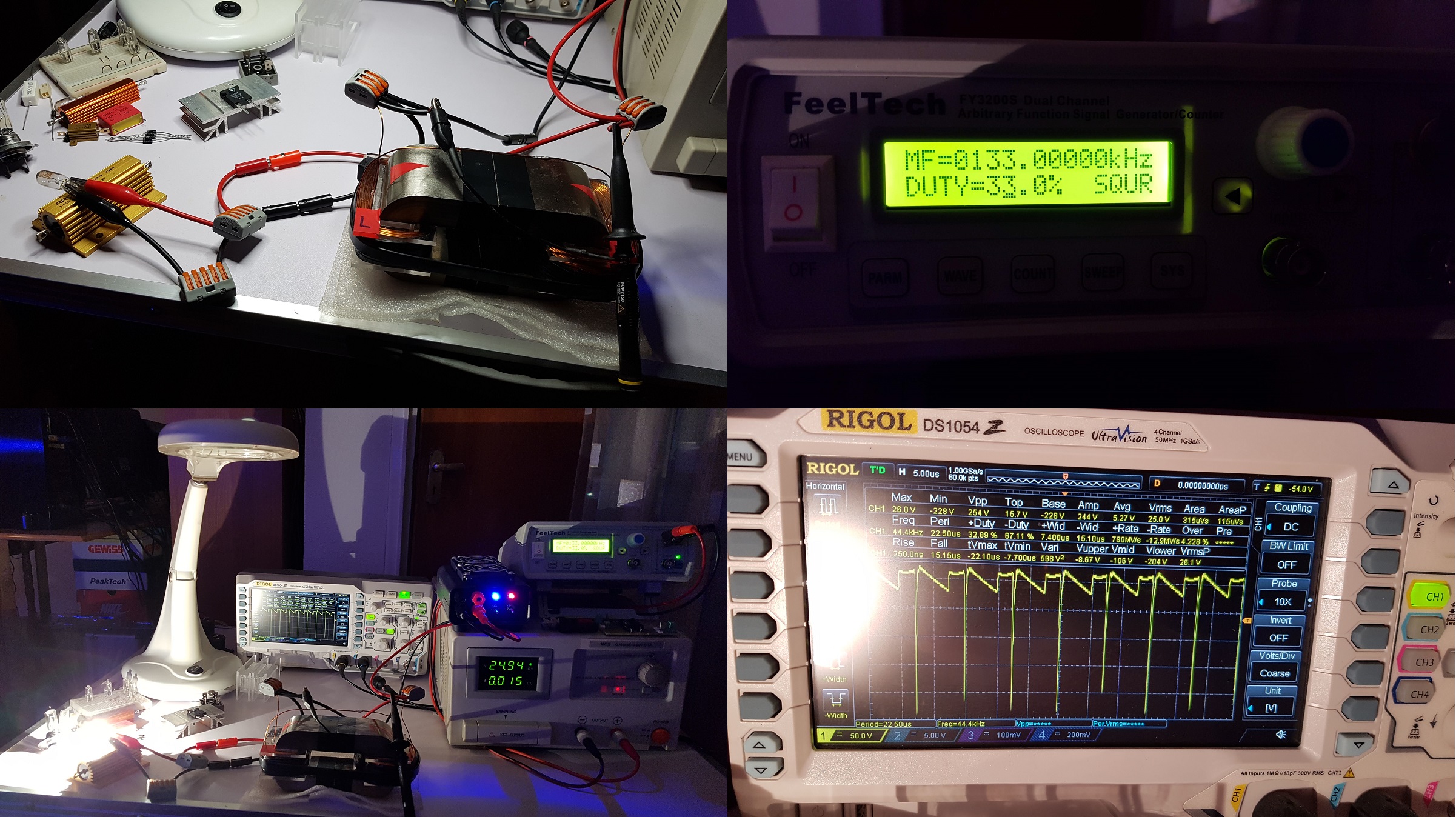
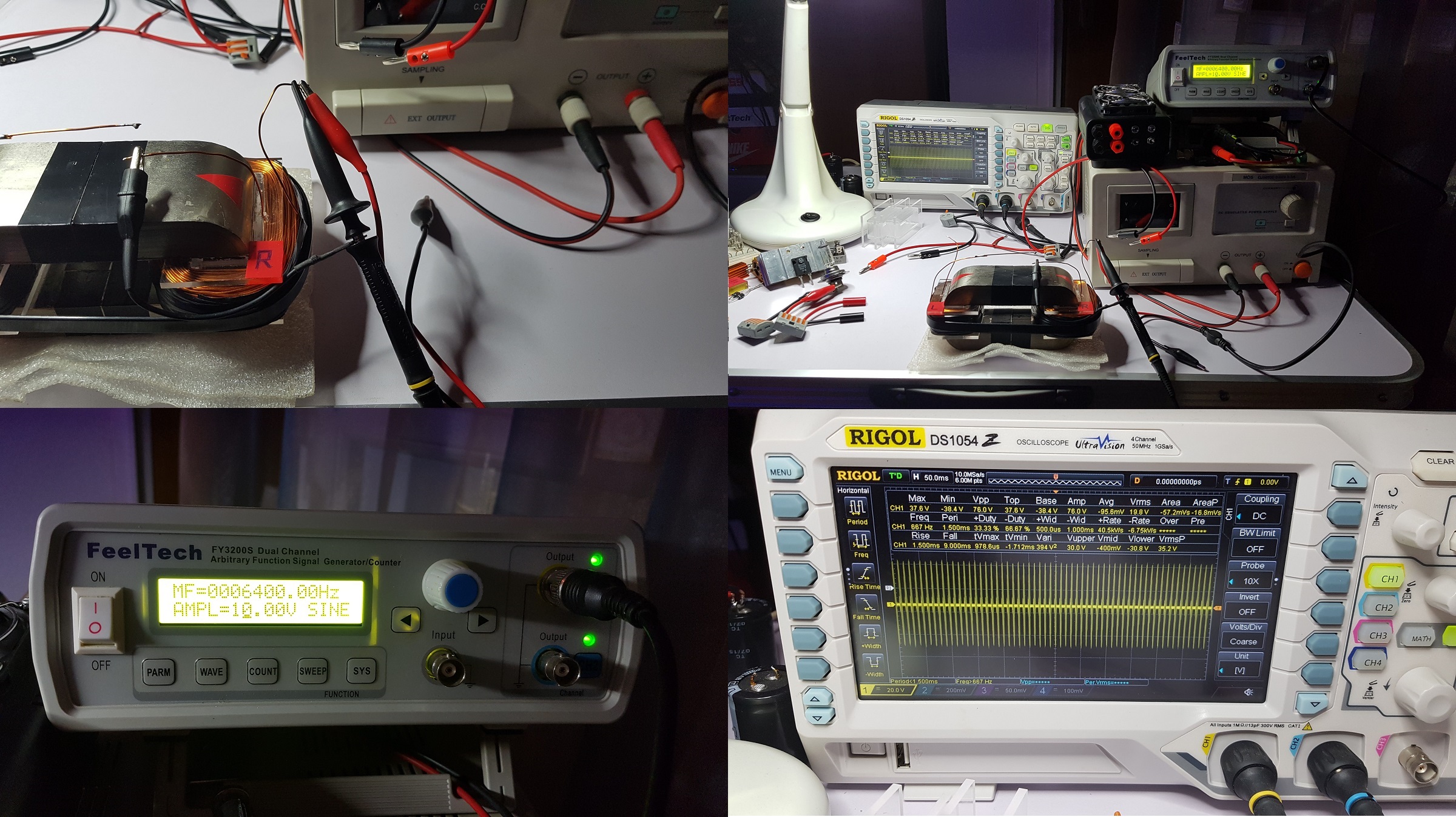
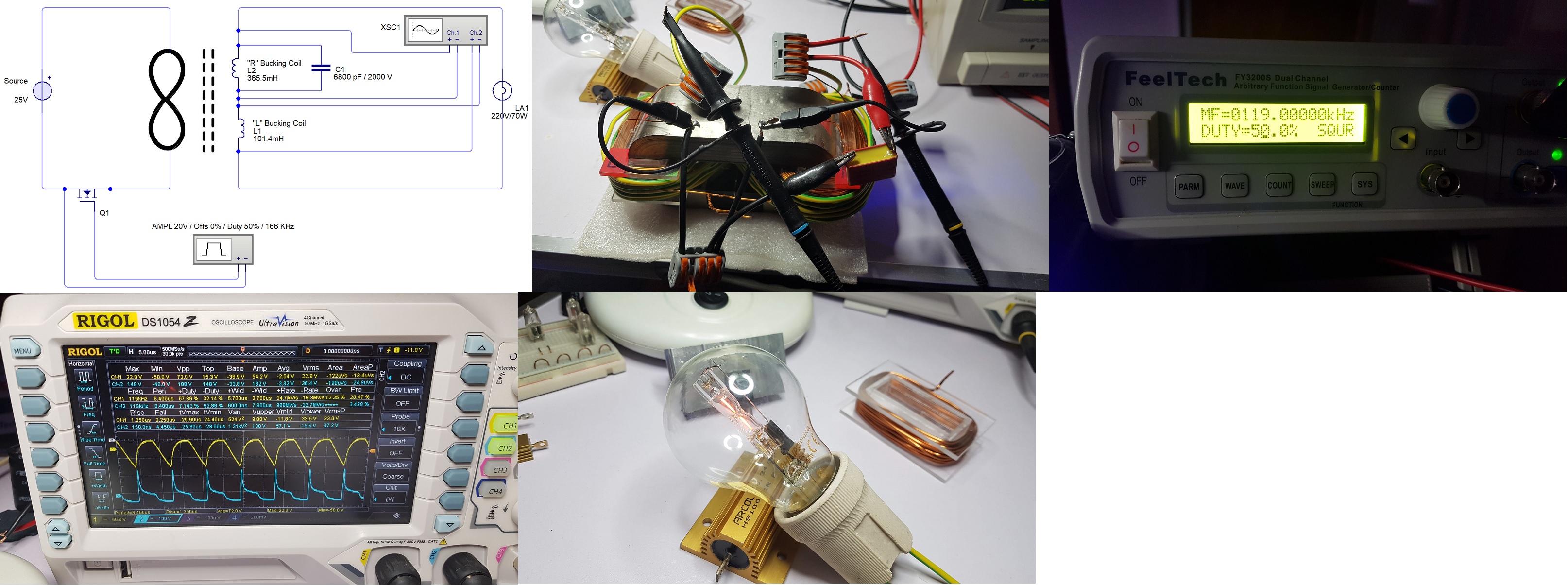
I was searching in the first ZPM thread for the parameters of the test showing on ZPM's output the waveform like Graham Gunderson's device output, just wanted to verify that the new ZPM is also capable of showing that pattern:

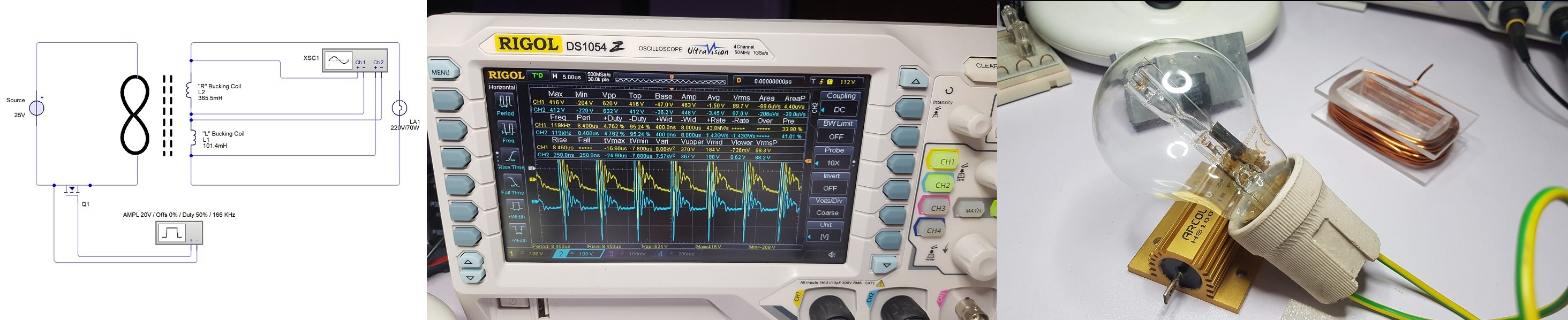
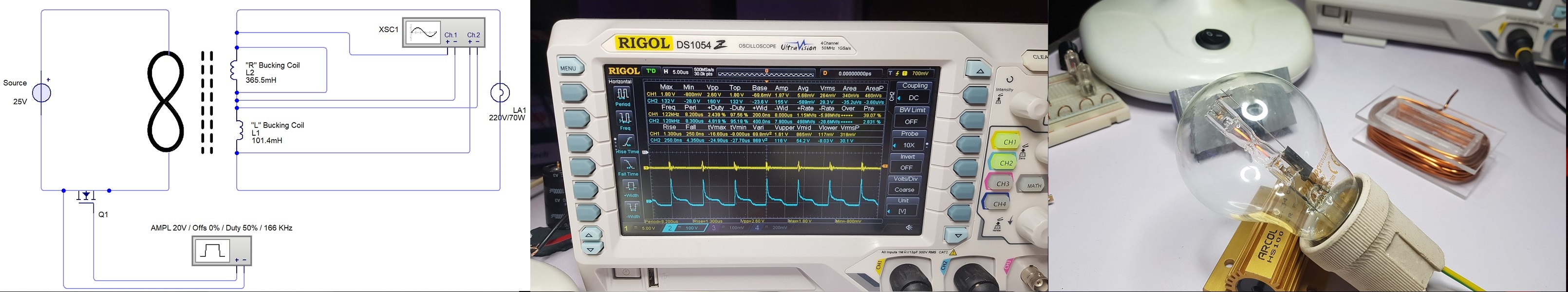
And this is the output measurement, it's the same as I posted it last night - looking like Graham Gunderson's device output:

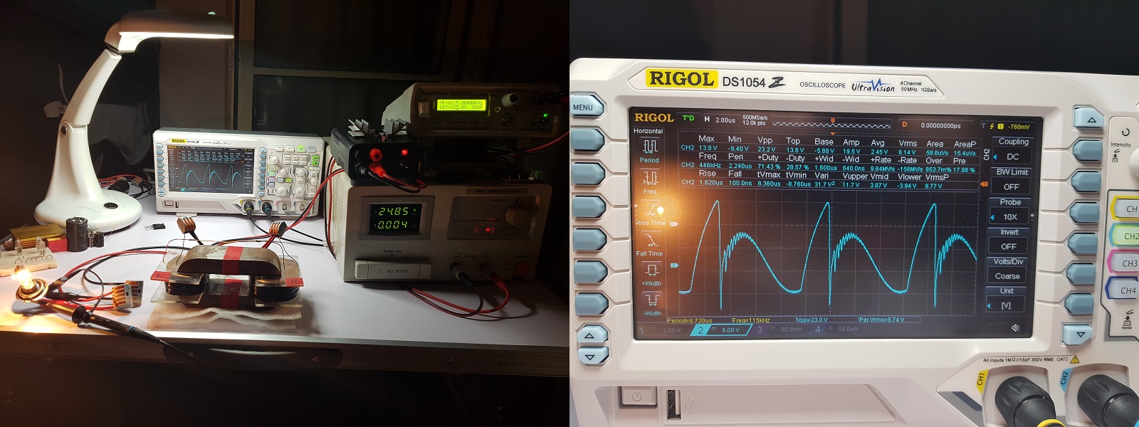
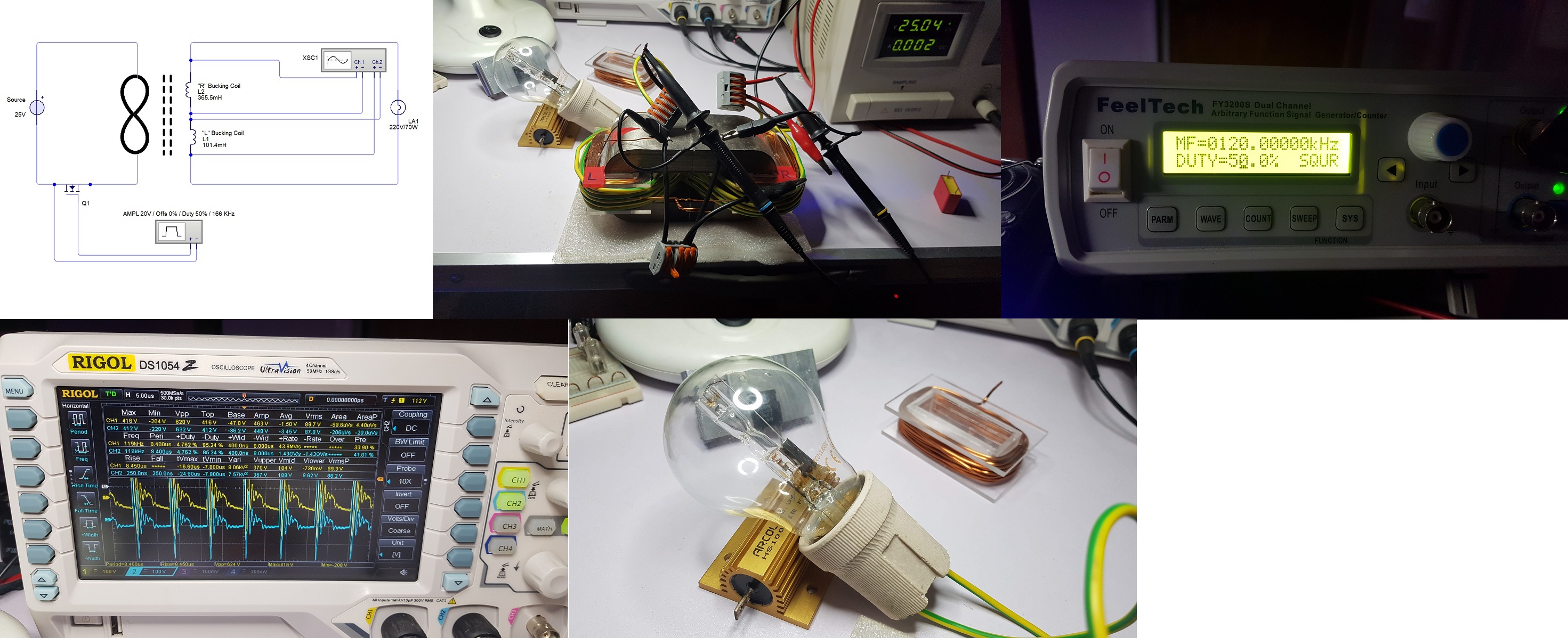
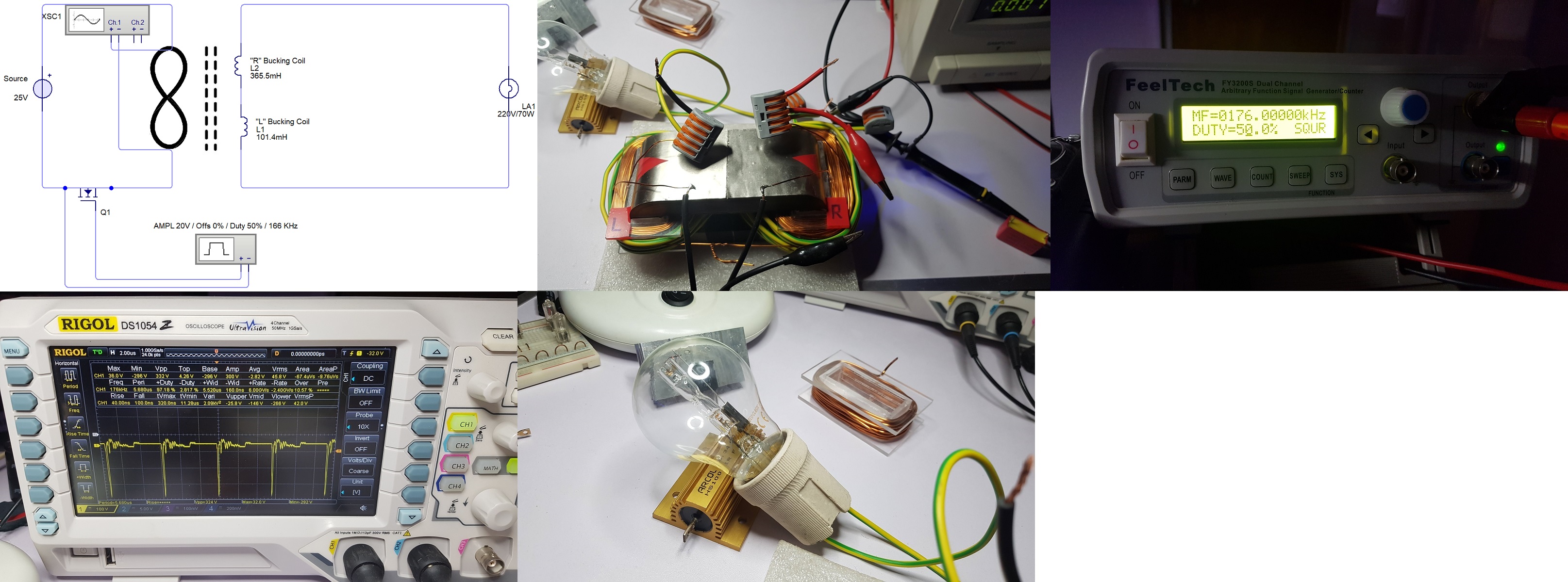
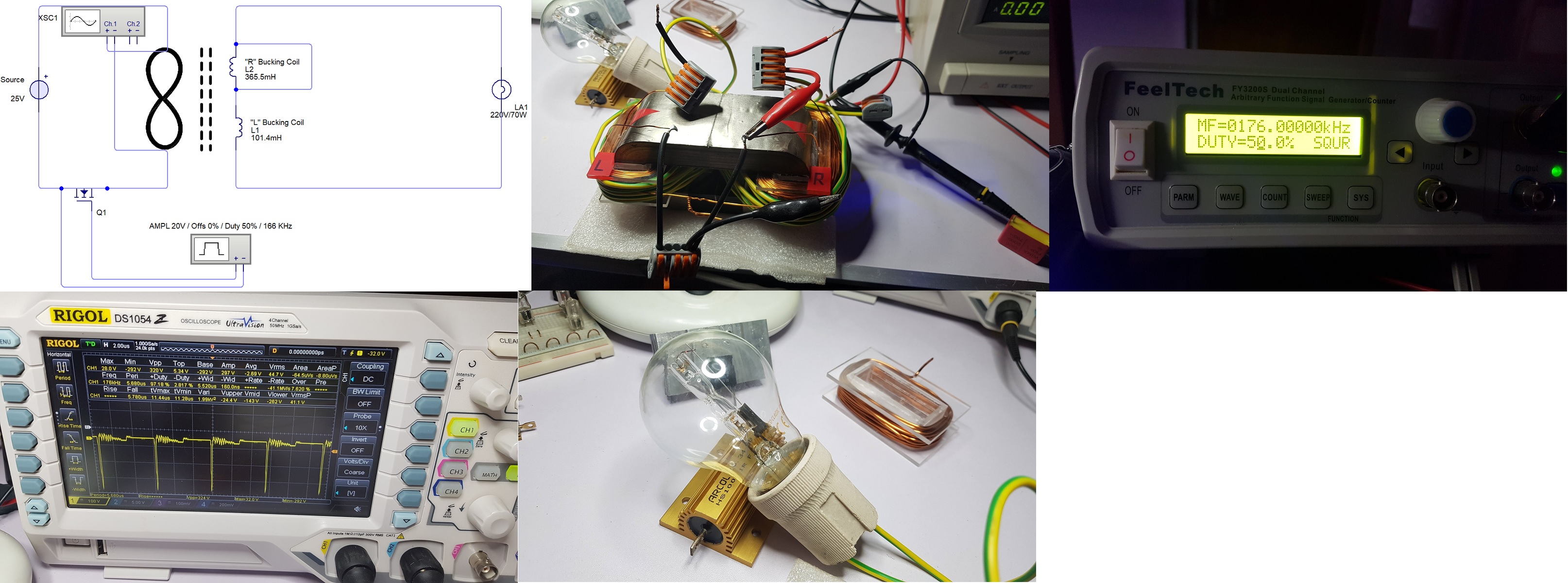
So the prototype was showing Gunderson's pattern at 115 KHz and 25% duty cycle using one 12V/55W light bulb on output.

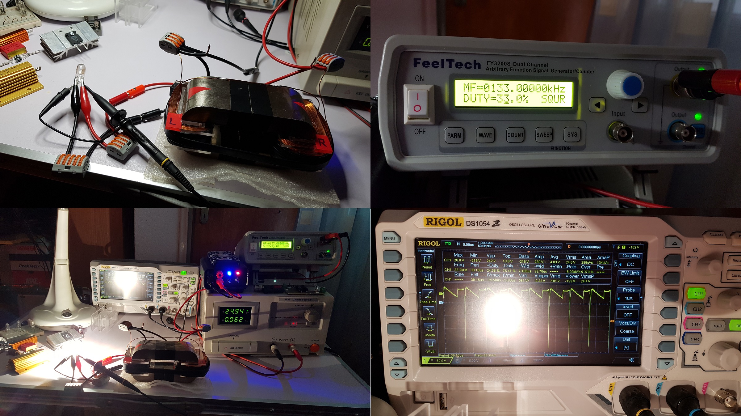
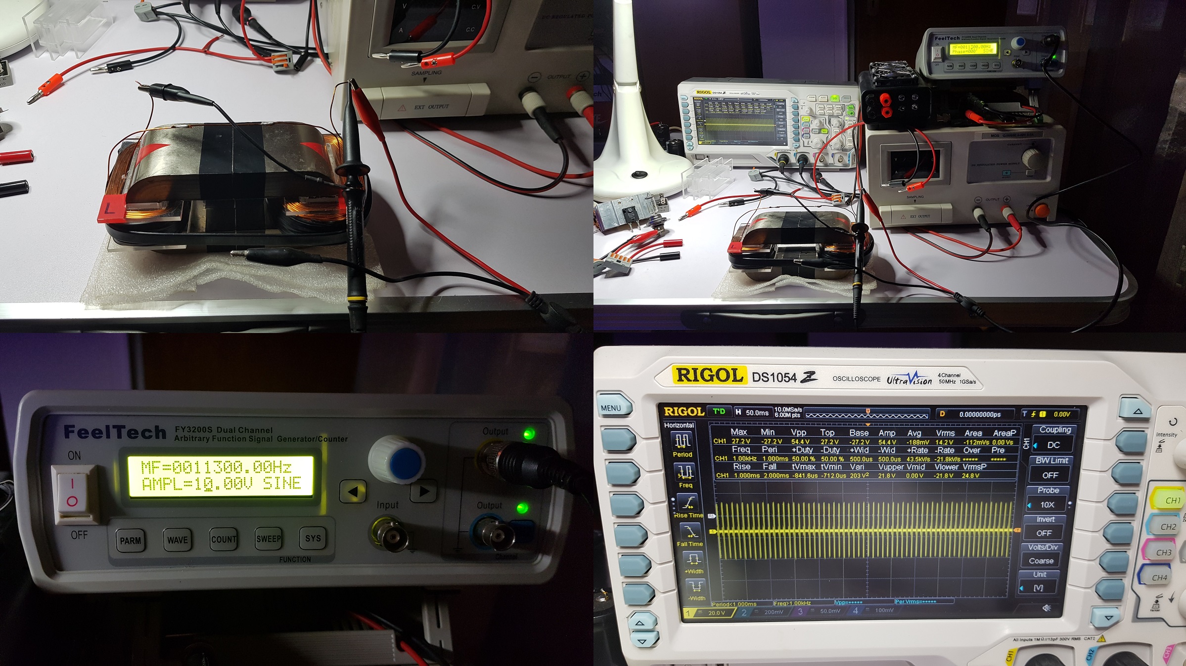
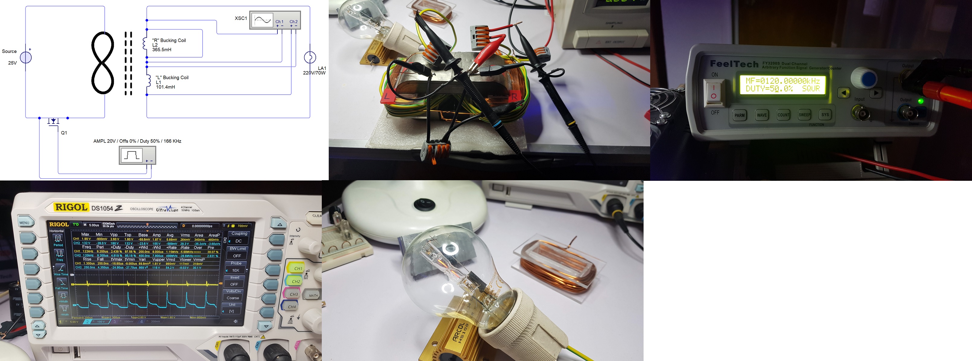
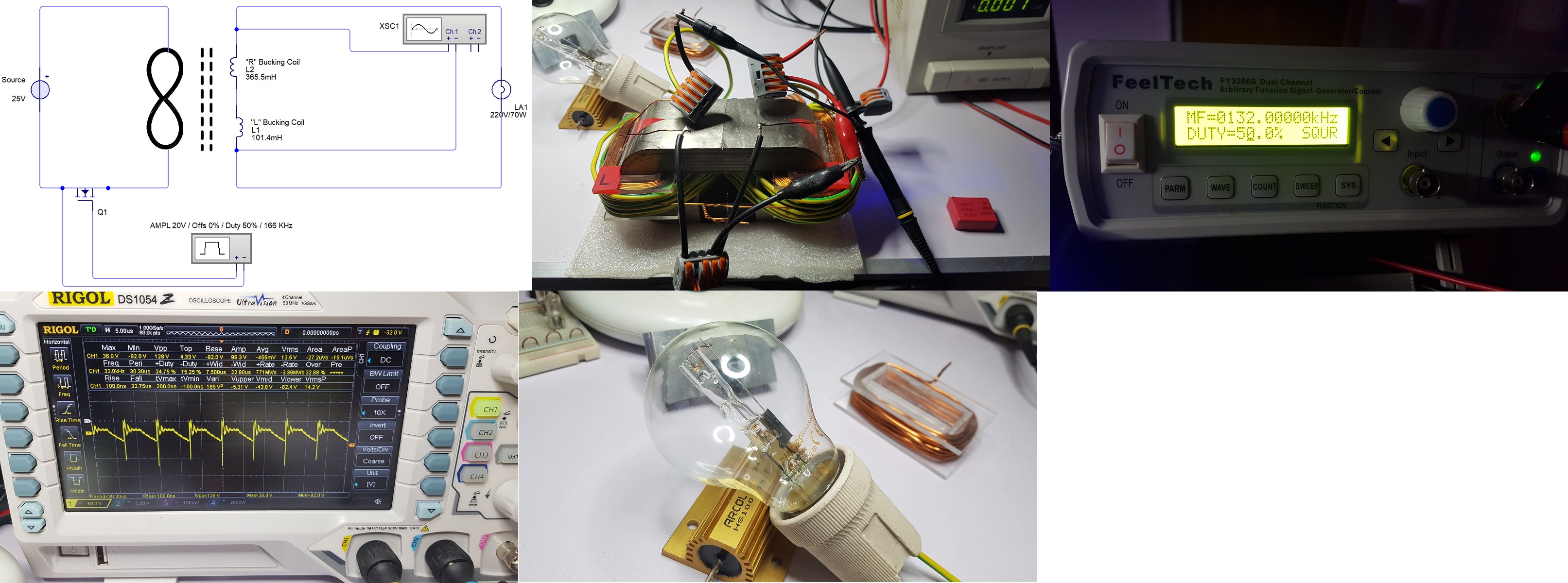
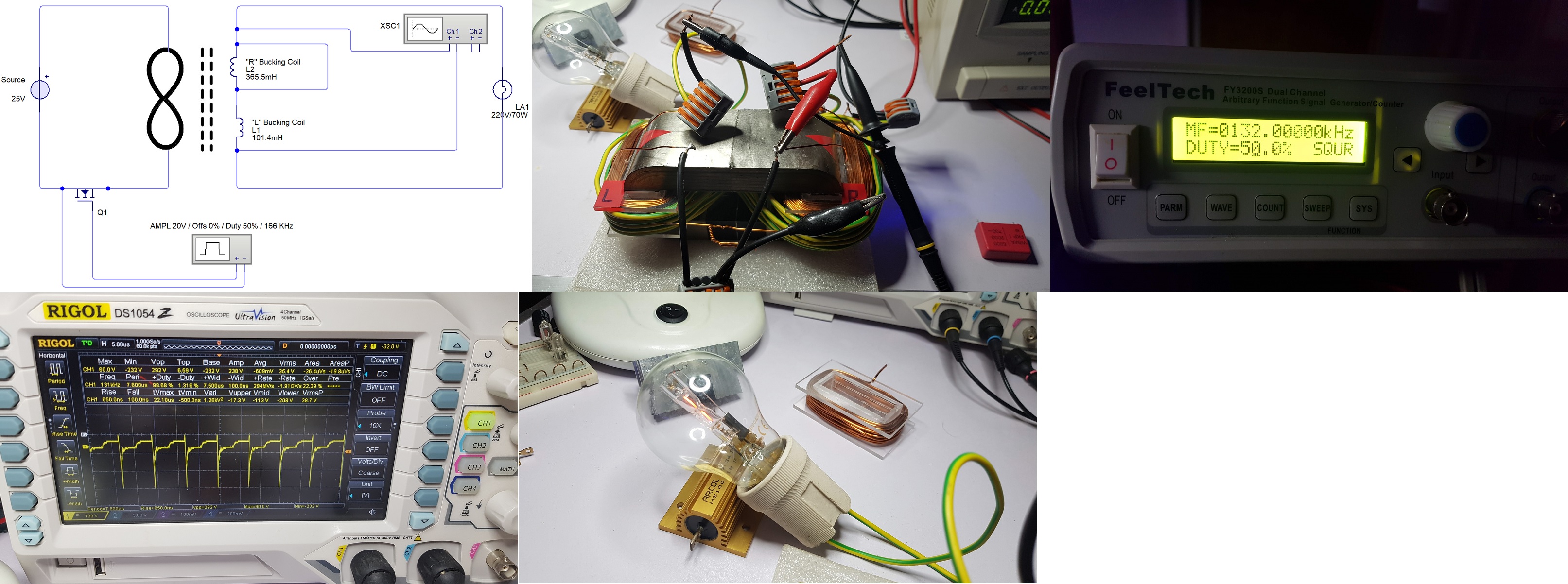
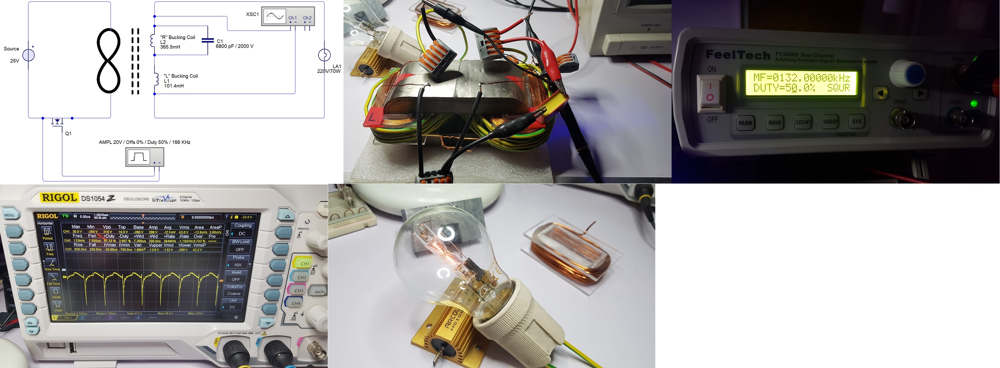
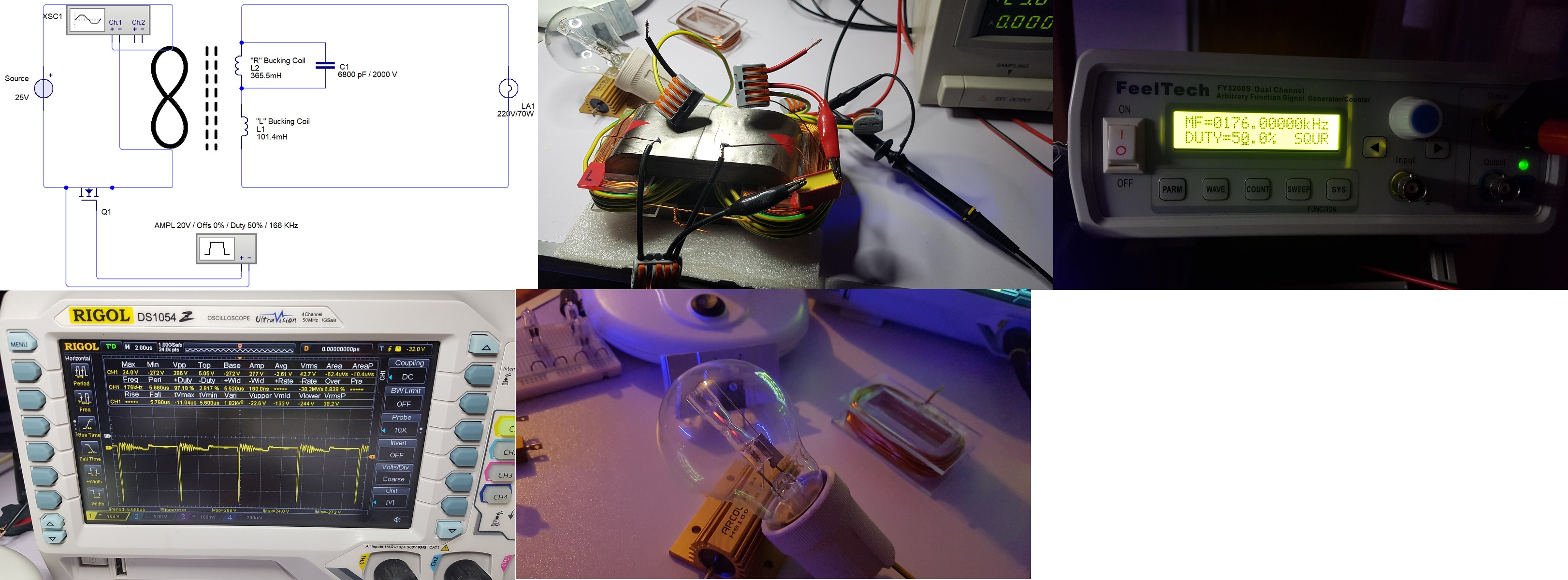
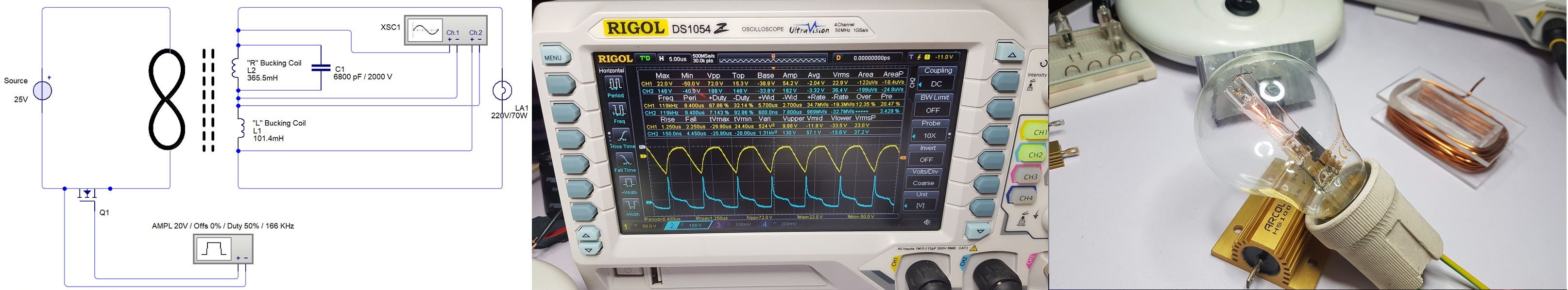
And this is the same test using the new ZPM:

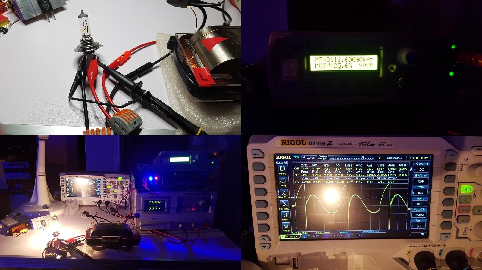
So the new ZPM has the same behavior at 111 KHz (instead of 115KHz) optimal frequency, a difference which I consider insignificant.

The only significant difference I keep thinking about is the big difference of inductance between the prototype and the replication for the bigger coil ("R"):

Edit: I just compared the inductance measured for each coil of the prototype long time ago and the inductance measured for each coil of the replica today:

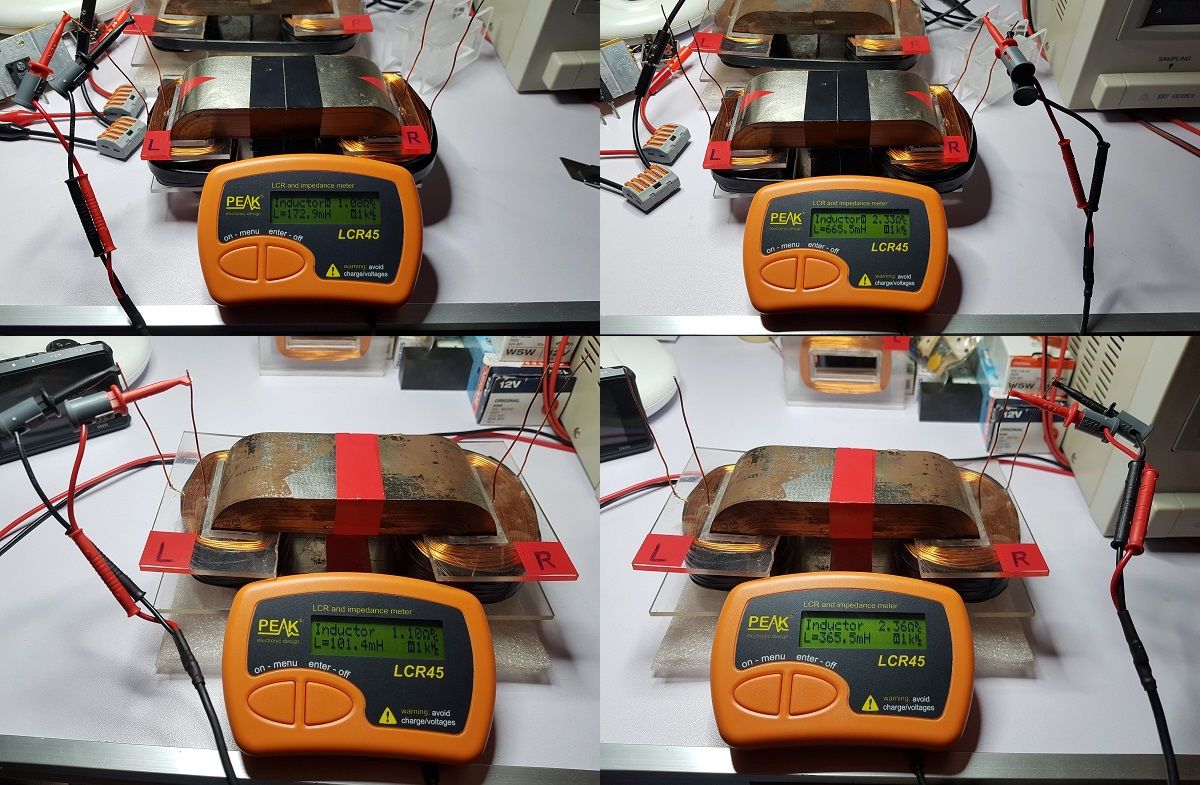
For the smaller coil ("L") I see 101.4 / 172.9 mH. Let's say this is normal as I made the coils tighter on the replica.

But for the bigger coil ("R") I see 365.5 / 665.5 mH. That's almost double inductance. I have no explanation of this difference so big.

I calibrate my LCR every time I make measurements, I calibrated it in that day and I calibrated it today.

Still, something seems wrong with the measurements of the coils characteristics.

I still have no explanation about this, I still don't know what's the cause.

In the end of this post I'm adding a image used by a guy named David Monroe in a Facebook group named "Understanding Tesla's Stationary Waves and Scalar Energy" to illustrate the behavior of the standing waves. I don't intend to post inappropriate content but the way he explains the image is like this: imagine the perturbation we make in the zero-point field as this girl jumping on the ground; the perturbation make the zero-point field oscillate in concentric waves around but, instead of propagating indefinitely away from the center, the concentric waves encounter the pressure/energy of the zero-point field and, at a certain distance from the source of the perturbation, instead of continuing to propagate they return back to the source of perturbation. The important thing is when they return to the center they contain the energy/pressure of the zero-point field which made them return to the source of the disturbance. That's the energy which is used by all over-unity devices to provide more energy on their output:

Ignoring the nice girl in the image I think the image and the explanation sounds like a good description of the standing waves and the way they can transmit energy from the zero-point field to the source of disturbance.

Chris, if you consider the image inappropriate for the forum let me know and I will remove it.

"If you want to find the secrets of the universe, think in terms of energy, frequency and vibration."
Nikola Tesla
Fighter posted this 10 March 2020

Hi guys,

Cd_Sharp asked me to run some tests for finding out the resonance frequencies for ZPM's coils.

I'm adding the results here for later references.

What I did was to insert a sinusoidal signal with AMP=10V and measure the frequency where coil's resonance is maximum in amplitude (note: the ground connector from the signal generator is not connected). Something like this:

So I disconnected the connection between coils and all the wires connected to ZPM and started testing.

This is the test for coil "L", the smaller coil:

This is the test for coil "R", the bigger coil:

Then I soldered again the connection between coils.

This is the test for coil "L" plus coil "R" together:

So the preferred resonance frequencies for ZPM's coils are these:

  • coil "L" (smaller coil): 11.9 KHz;
  • coil "R" (bigger coil): 6.4 KHz;
  • coil "L" + "R": 11.3 KHz.

"If you want to find the secrets of the universe, think in terms of energy, frequency and vibration."
Nikola Tesla
  • Liked by
  • AlteredUnity
Fighter posted this 22 April 2020

Hi guys,

I hope everyone is okay.

I know the world is in a bad shape right now but we must remember how to laugh again, this is how we Romanians survived over 50 years of communist darkness - we were making jokes and laughing about it.

So a joke about the current situation:

And in a more serious and realistic way:

Now going back on the subject, I'm posting some updates with a promising experiment using a different experimental configuration of ZPM.

I tested many configurations while trying to build a input coil separated from the output coils. Also switched to a 220V light bulb on output.

The results are not spectacular but I consider them a good beginning of the enhancements stage.

As it's difficult to describe the current configuration and behavior of ZPM in words I thought it will be more clear if I make a video presenting it. I know I'm not a good speaker but I don't intend to become one, my intention is just to present my findings.

So this is the video:


The current question is why putting the bigger coil ("R") in short provide more energy on output and also why putting the capacitor in parallel on the same coil is providing more output than shorting the coil. Kind of makes no sense as putting a coil in short should make it "disappear" (so to speak) from the configuration.

I don't have answers to these questions right now but when I find some time I intend to get screenshots of the oscilloscope with the probes on "L", "R" and input coils for each scenario (coil "R" not in short-circuit, then in short-circuit, then with capacitor on parallel on coil "R") and try to see what exactly makes these differences. I'll post the updates here.

Also I'll continue changing the configuration and test, trying to get better results. This was the reason why I created the ZPM replica - to experiment on it without dismantling the ZPM prototype which is stored in a sealed container for now to limit the contact with the air and the rust of its core.

Stay safe everyone.

"If you want to find the secrets of the universe, think in terms of energy, frequency and vibration."
Nikola Tesla
  • Liked by
  • AlteredUnity
Fighter posted this 25 April 2020

For later references I'm posting here the analysis of the latest configuration with measurement schemas, oscilloscope probes placements, frequency, oscilloscope screenshots and photos of the 220V light bulb  for each test:

1. Oscilloscope probes are connected to coils "L" and "R" with oscilloscope ground connected on the connection between coils (the yellow channel is bigger the coil "R", the blue channel is the smaller coil "L"):

  • simple configuration (no short-circuit on coil "R", no capacitor in parallel with coil "R"):

  • short-circuit on coil "R":

  • capacitor in parallel with coil "R":

2. Oscilloscope yellow probe is connected to output (coil "L"+"R"):

  • simple configuration (no short-circuit on coil "R", no capacitor in parallel with coil "R"):

  • short-circuit on coil "R":

  • capacitor in parallel with coil "R":

3. Oscilloscope yellow probe is connected to input coil:

  • simple configuration (no short-circuit on coil "R", no capacitor in parallel with coil "R"):

  • short-circuit on coil "R":

  • capacitor in parallel with coil "R":

It's a lot to analyze in this data but somewhere in the oscilloscope screenshots is the answer to the question "why short-circuiting coil "R" or putting a capacitor in parallel with it provide more energy on ZPM's output ?" and hopefully some hints on how to amplify this effect further.

If you notice something in the oscilloscope screenshots please let me know.

Also something I find strange is the fact that on the input coil I have more than 300 Vpp and more than 45 Vrms, I should have just 25 Vrms as provided by the DC source, is that back-EMF ? Is it how ZPM as usually is sending power back to the DC source ?

Many questions but finding answers to them will lead to further enhancements of the device.

"If you want to find the secrets of the universe, think in terms of energy, frequency and vibration."
Nikola Tesla
Fighter posted this 25 April 2020

1. Initial:


2. Bigger coil "R" short-circuited:


3. Capacitor put in parallel with the bigger coil "R":


Looking at the oscilloscope data I see major changes in coils' behavior between the testing scenarios.

Here should be the key of the effect and hopefully some hints on how to enhance it.

"If you want to find the secrets of the universe, think in terms of energy, frequency and vibration."
Nikola Tesla
UndisclosedMember posted this 25 April 2020

Hey Fighter,

My Friend, EXCELLENT WORK! I sent you a Donation to help out! If more donated, then we would be able to do more work, share more! Right now times are tough! But right now we have an opportunity like we have never had before! We can come out of this Virus issue into a Changed World! We will come out of this into a Changed world! Lets make the required changes!

I urge everyone, Fighter has shown excellent results! His first machine was 3 Watts above the Unity Boundary!

If everyone just donated a little, this work could go so much quicker.

Lets Change this world for the better! Lets push for the Advancement of Humanity!

Fighter posted this 26 April 2020

Thank you.

We have some fine builders here but we need more. We should put our experimental data together in order to push forward. On my side I was very curious how YoElMiCrO's replication of ZPM works and I was looking forward to see some testing data, having a ZPM replica tested with a different setup (DC source etc.) would be very helpful. Sharing is the key, that's why I continue to share my findings but there are too many directions/configurations which should be explored and I can't go to all these directions on my own, I can build just one configuration at a time (as I find some free time) and testing it takes a lot of time. For example I found this effect but learning how it can be enhanced will take some time and experiments. Who knows what other effects are waiting to be discovered in other configurations ? We need data sharing and more experiments.

"If you want to find the secrets of the universe, think in terms of energy, frequency and vibration."
Nikola Tesla
YoElMiCrO posted this 26 April 2020

Hello fighter.

First apologize for the time you have spent publishing my findings, you have
sense because to understand it I had to carry out many experiments with circuits
to demonstrate the hypotheses that occurred to me along the way.
I tell you that the tests I carried out on your ZPM were on a small scale
for not having large amorphous core, only a few cores used
to measure alternating currents, but enough to understand
partially what was happening, like the magnetization/demagnetization energy phases,
the energy/mass density and stuff like that.
Your system shows that N.E. Zaev is right, only that you went further
using bucking coils and in relation to 0.25.
I'm still a bit complicated to work, but I almost have an article
realized that it talks about your ZPM even though all the systems share
the same phenomenon.
This week I will make a little time to finish it, so I can publish it
here, then I will put an article in Tier II and of a deeper theoretical nature
so we can all debate its veracity with simple experiments
until we finally have at least one working flashlight.

Thank you in advance.

YoElMiCrO.

UndisclosedMember posted this 26 April 2020

Hey YoElMiCrO,

Who is N.E. Zaev, and what is it you think he is right about? Never heard of this person. Is the following what you are referring to:

History notes
N. E. Zaev’s article about using environmental heat to generate electricity was published
somewhere in 1991. According to some internet resources, N.E. Zaev was researching this
concept since 1960s, probably in cooperation with P.K. Oshepkov, founder of Public Institute of
Energy Inversion. I heard first time about Zaev’s idea of conversion of environmental heat to
electricity about ten years ago. Since that time I made a lot of experiments and attempts to build
such device without any significant progress. In desperation, I started studding everything related to magnetic properties, BH curves etc. And accidentally, last year a chain of unexpected events was triggered, which brought me to understanding and some experimental results. Here, in this short summary, I am trying to document a path which one have to follow in order to be able to understand and build such device.

Interesting!

Attached Files

Close