Romanian ZPM (Zero Point Module) - Enhancements Stage

  • 4.1K Views
  • Last Post 28 November 2023
Fighter posted this 13 February 2023

This is the second imported thread (from the old aboveunity site) about my ZPM:


For references I will keep the original posting date for every imported post.

Note: This thread is public, everyone can see it, even the visitors which are not members here.

For the posts made by former aboveunity members which are not members on our site I'll use a member placeholder named UndisclosedMember.

Regards,

Fighter

"If you want to find the secrets of the universe, think in terms of energy, frequency and vibration."
Nikola Tesla
YoElMiCrO posted this 28 February 2020

Hi All.

@Fighter.

I have time for the ZPE device, is the best example on the net for AU.

Thank, for sharing.

YoElMiCrO.

Fighter posted this 29 February 2020

Hi YoElMiCrO, thank you. I'd be glad to know how your replication behave and what's the results of your tests.

You're more than welcome to post the details here (it's about the same device) or if you prefer in your own replication thread, you choose.

I'm currently working also on a ZPM replication but unfortunately the progress is very slow because I'm very busy at work and don't have too much time. I'm always telling myself "maybe I'll have some time in the weekend"...

I'm looking forward to see the test results of your ZPM replication, thanks for sharing.

"If you want to find the secrets of the universe, think in terms of energy, frequency and vibration."
Nikola Tesla
cd_sharp posted this 29 February 2020

Hey, my friend

I watched again your video 


I noticed you are using 5V amplitude from the SG. Based on Vidura's recommendations,

If any signal source with a different voltage as 5V default configuration will be used , changing the current limiting resistor of the emitter diode may be required. Choose an adequate value to adjust the emitter current between 10 and 16 mA.

I determined that for FY3200S SG using 10V amplitude is optimal.

If you are using 5V, the MOSFET may not open fully.

Just thought to let you know this detail.

Best wishes

If you know how to build such a device and you're not sharing, you're a schmuck! - Graham Gunderson

Fighter posted this 01 March 2020

Hi my friend,

Yes, it's true, I used the minimum AMP where I observed the light bulb is on while I was testing the switching functionality at low frequency with a light bulb instead of ZPM. I didn't wanted to go higher with AMP because I was afraid I'm gonna damage the switch.

For the switch made by me (the black box on top of the DC source) I'm using maximum AMP=20V because I observed (based on light bulb's luminosity on ZPM's output) that is the most efficient value.

Thanks, I'll keep in mind this value (AMP=10V) when I'll use Vidura's tool.

"If you want to find the secrets of the universe, think in terms of energy, frequency and vibration."
Nikola Tesla
Fighter posted this 04 March 2020

Adding a quote from Nikola Tesla I found recently, I want to have it in this thread:

"If you want to find the secrets of the universe, think in terms of energy, frequency and vibration."
Nikola Tesla
Fighter posted this 07 March 2020

Hi guys, I have multiple updates.

First, I found out why long time ago ZPM destroyed the electrolytic capacitor from one of the channels of my bridge rectifier using MBR 4045 PT Schottky diodes: they are not fast enough to rectify so the capacitor is actually receiving negative voltage on its positive terminal. As you know I replaced the electrolytic capacitors of my rectifier with new 680uF/400V capacitors and tried again.

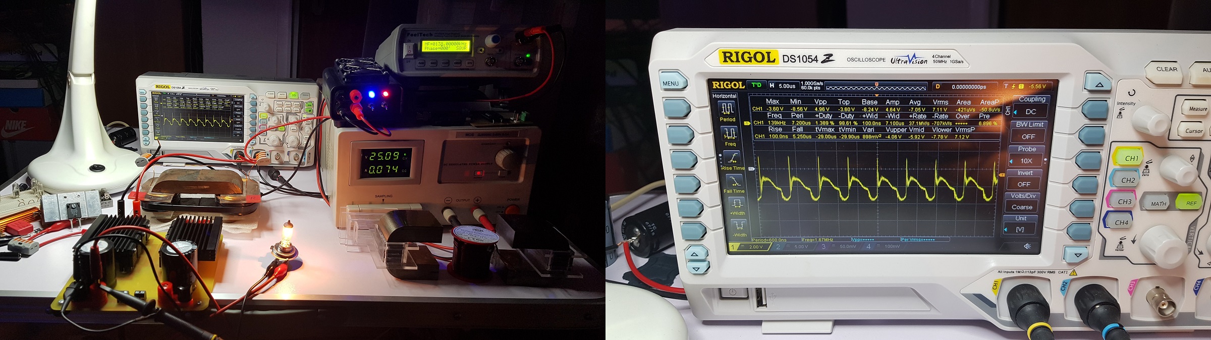
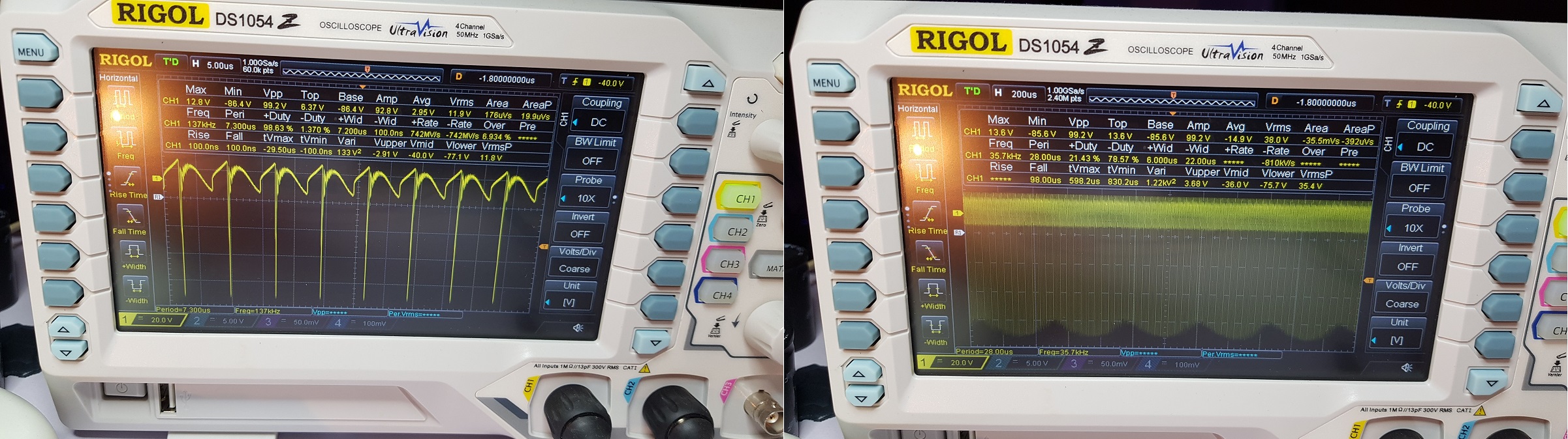
This is without rectifier just having the oscilloscope's probe on light bulb's terminals:

And this is with the rectifier on ZPM's ouptut:

As you can see the diodes in bridge fail to rectify and we have negative voltage on capacitor's positive terminal.

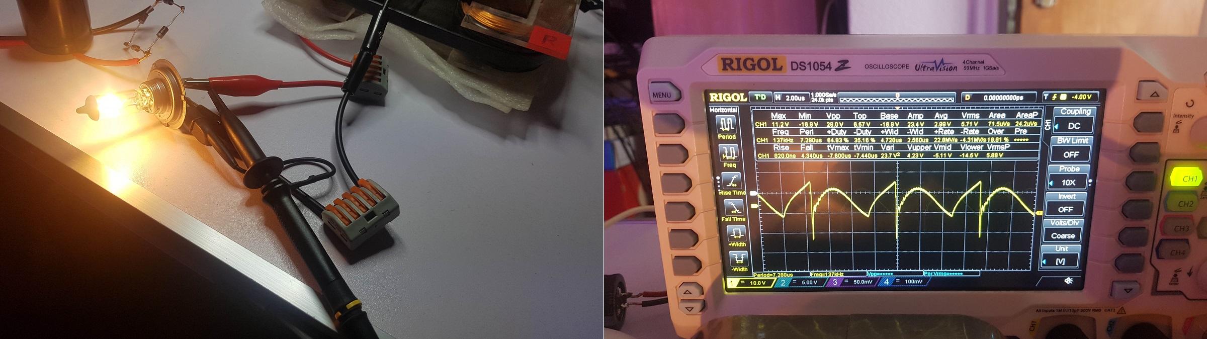
Then I tried with a improvised bridge rectifier using faster diodes (SF 28 G) and the good thing is these diodes rectify but the bad thing is they get hot very fast (within about 5-10 seconds) so they can't be a permanent solution:

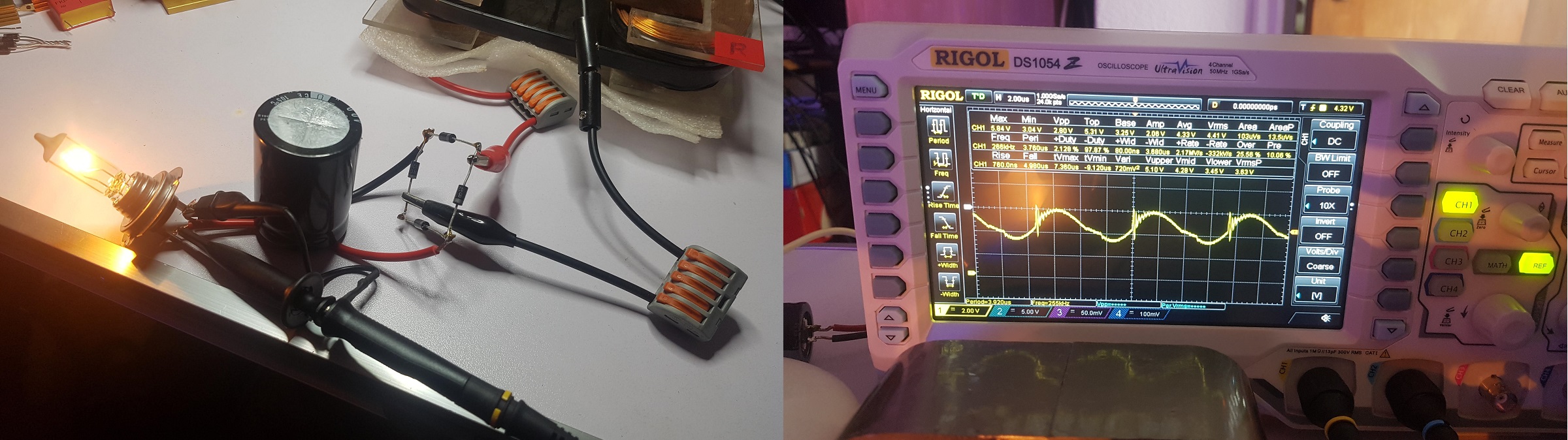
So I should try to find diodes like these but witch don't get hot so fast and so strong (after all it's a lot of energy wasted from ZPM's output). I need to search for those better diodes.

Another really good news is the fact that the ZPM replication is ready and is functioning just like the prototype:

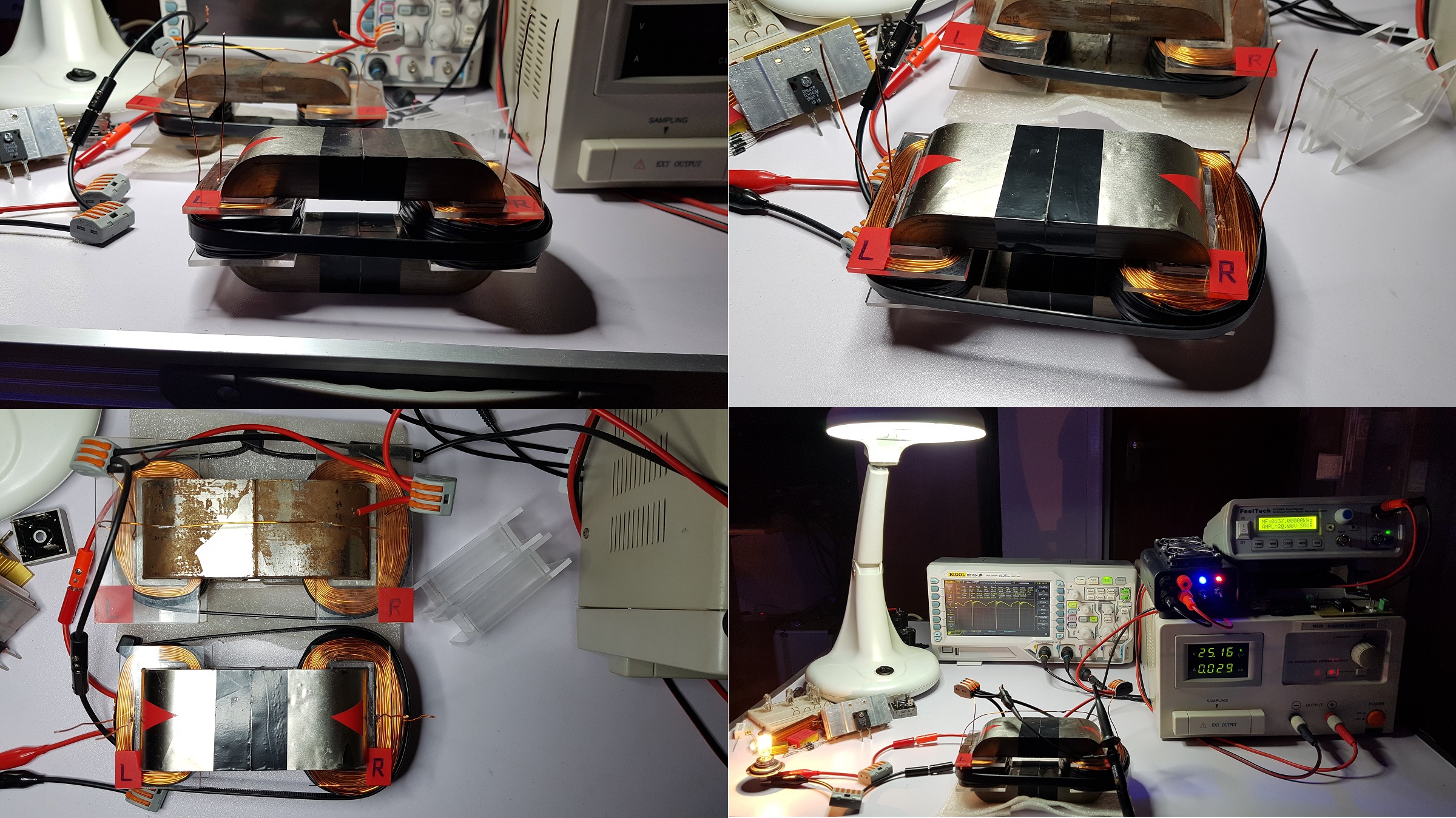
So the prototype can be replicated and now I have actually two functional ZPMs.

I'll document the building process below.

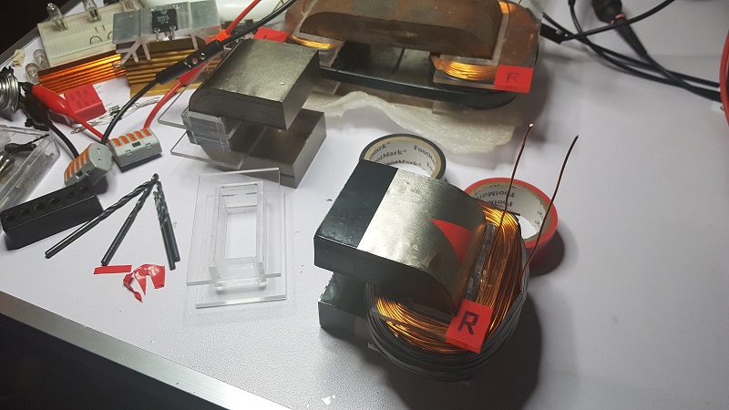
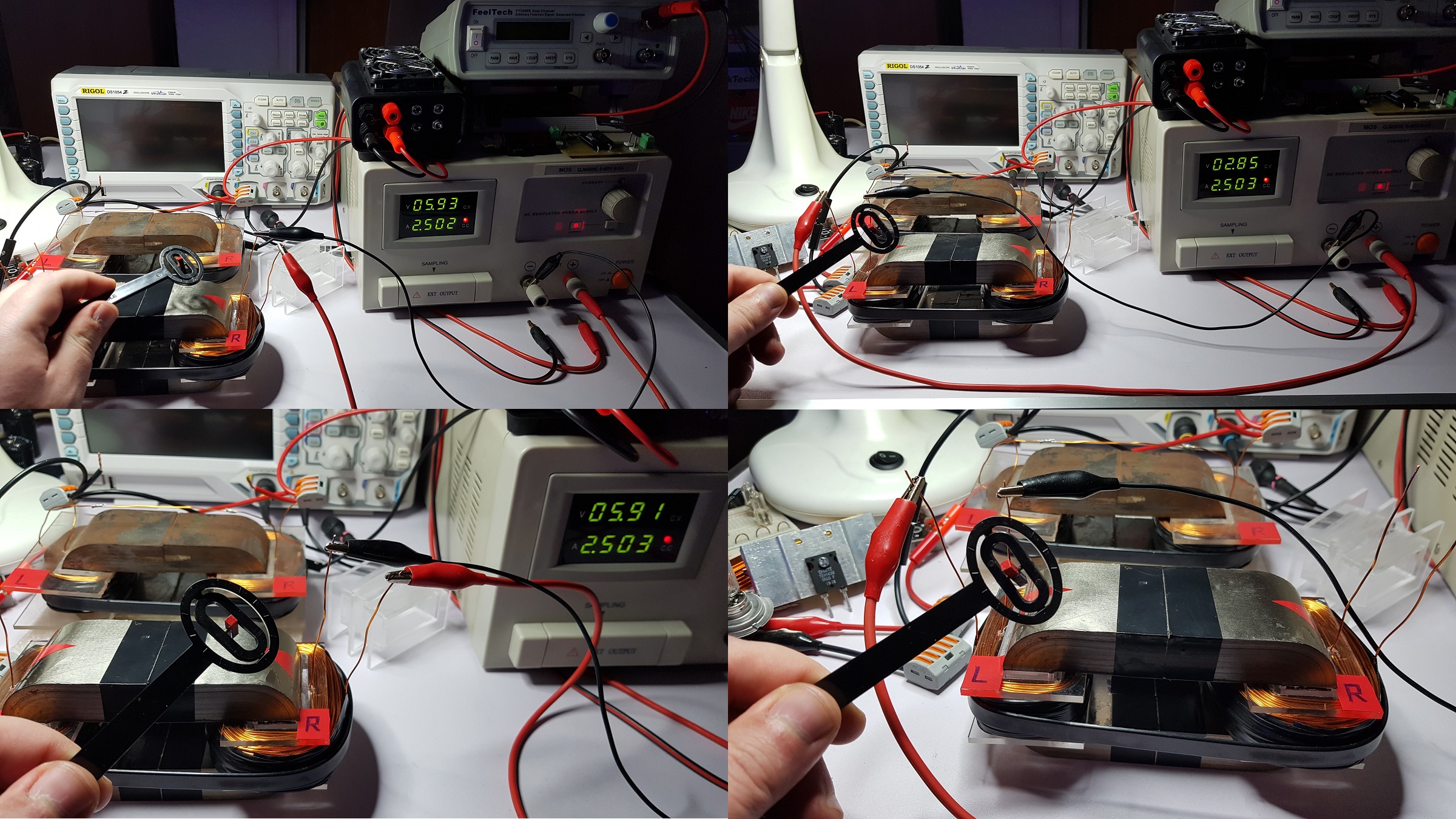
This is the step where I check the polarity of the magnetic field for each coil so I know how to connect the coils between them so I make sure on the top of the ZPM are two North magnetic polarities opposing each other:

The coils are exactly 150/300 turns using 0.8mm wire, considering the coil supports are smaller than the ones of the prototype I tried to build the coils tighter.

In the next step I calibrated my LCR and measured the characteristics of the coils.

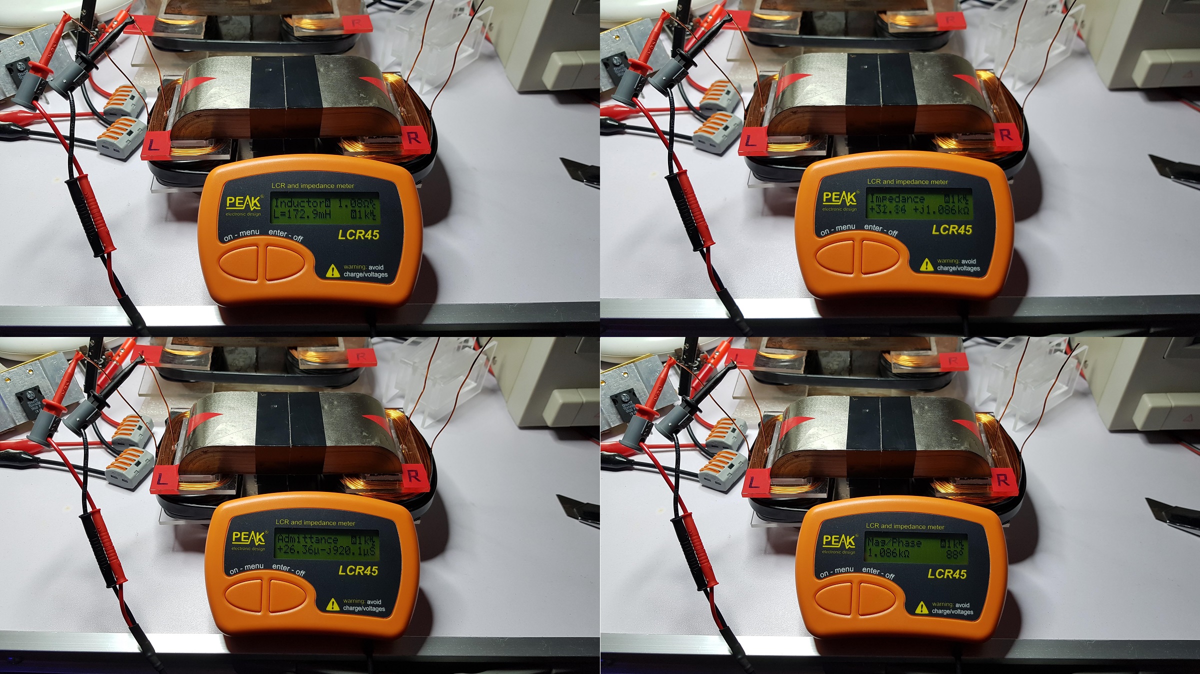
The characteristics of the bigger coil ("R") are these:

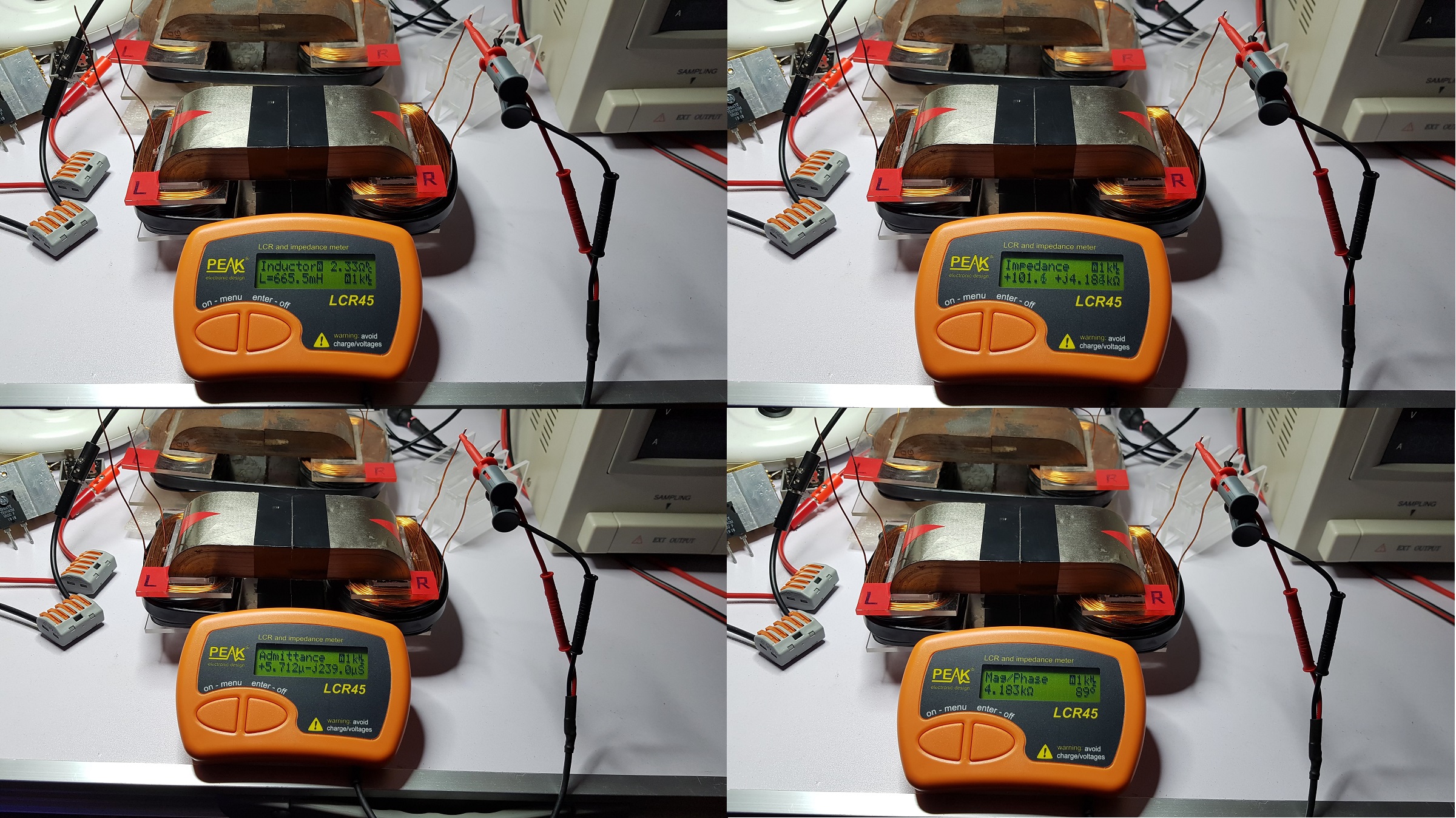
The characteristics of the smaller coil ("L") are these:

During the frequency sweep I found that the optimal frequencies of the device are almost identical with the frequencies of the prototype (just few KHz difference).

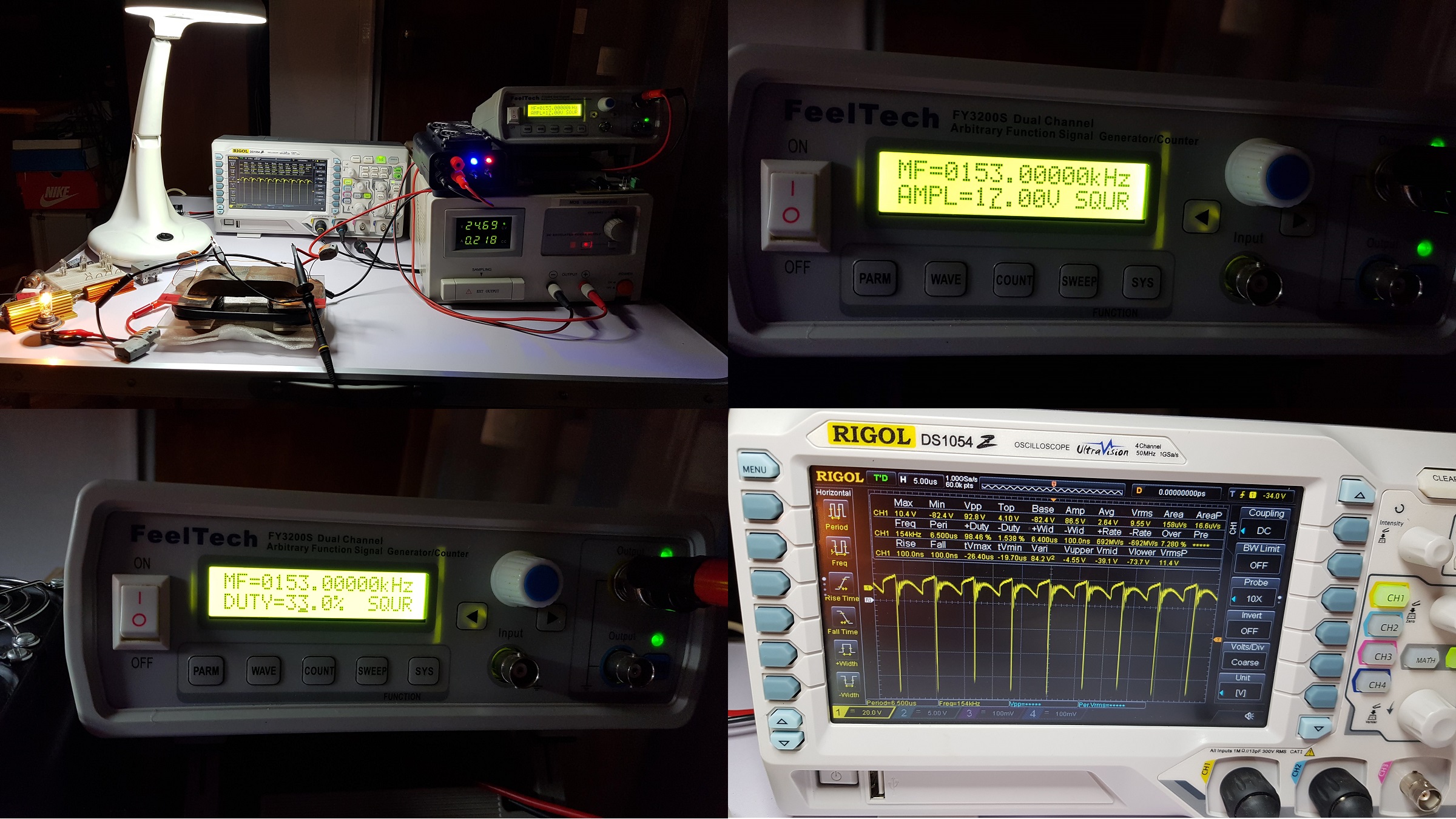
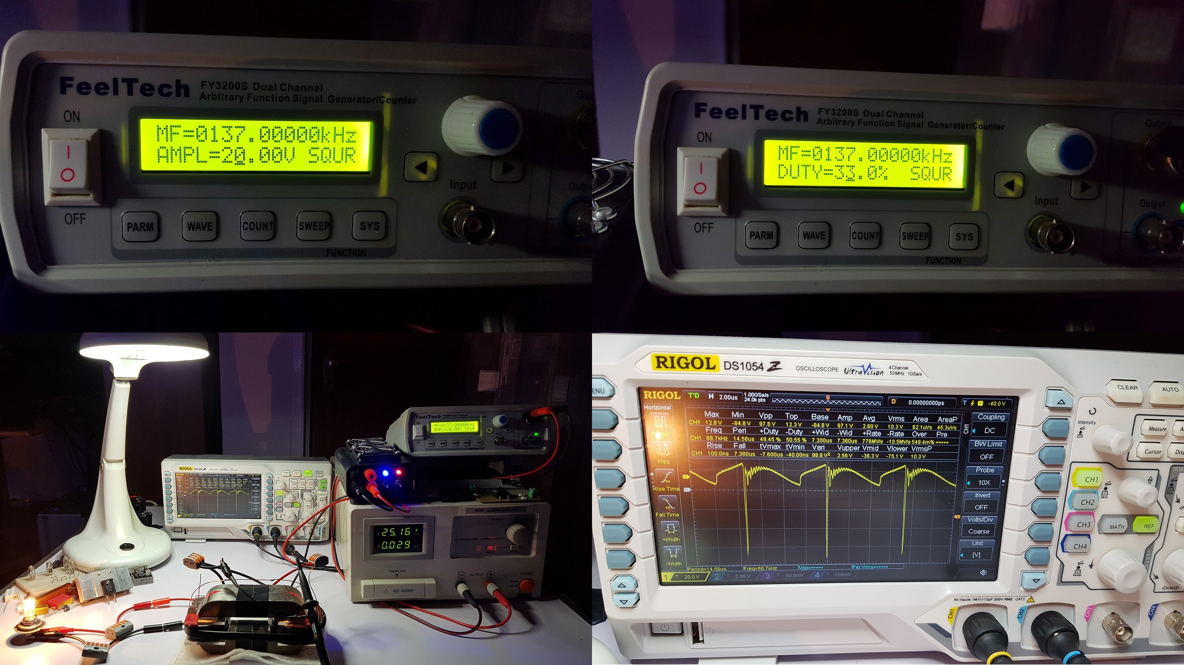
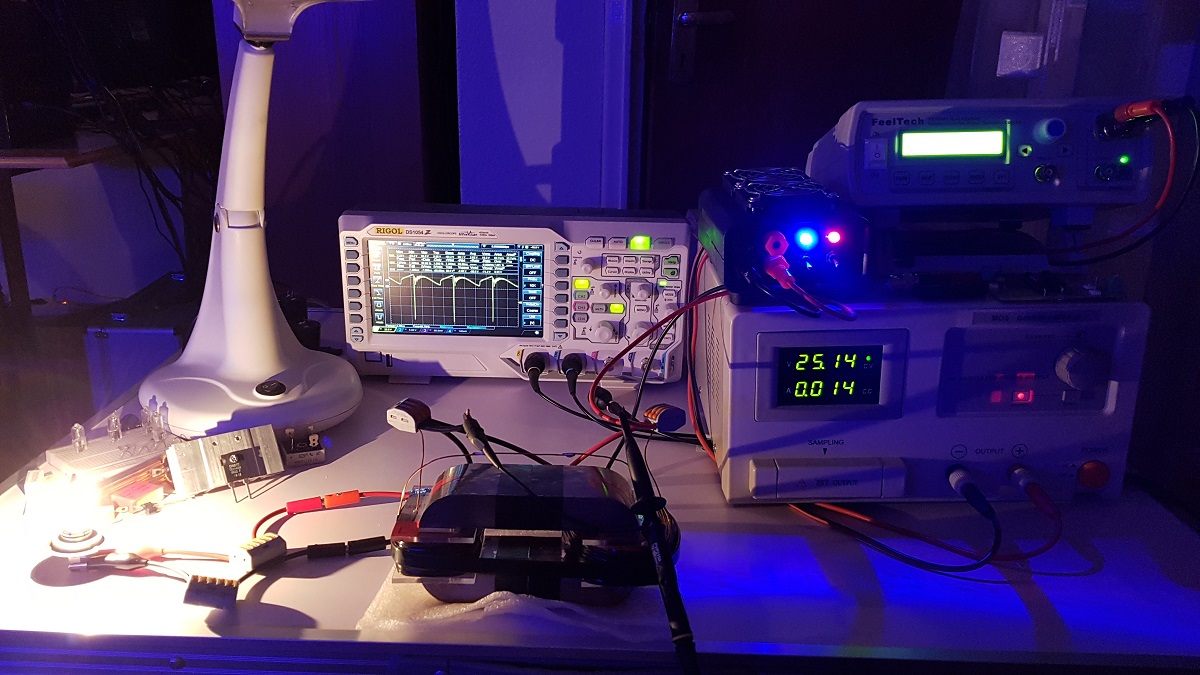
Below is a test with a 12V/55W light bulb on ZPM-2's output, let's name it this way:

And two more photos of the output on the oscilloscope:

So ZPM can be replicated. I placed the prototype in a sealed bag, I hope this will minimize the advancement of the rust on the Metglas core. I'll use it in experiments when it will be necessary, if I find differences in behavior of the new ZPM.

I'll use this new ZPM for enhancements (modifying the coils, additional coils and so on).

Another photo with the desk lamp off to check the luminosity of the 12V/55W light bulb:

Edit: I just compared the inductance measured for each coil of the prototype long time ago and the inductance measured for each coil of the replica today:

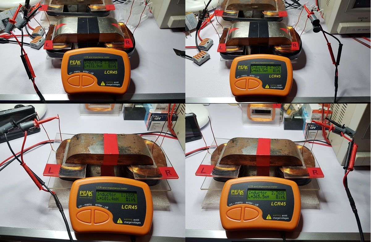
For the smaller coil ("L") I see 101.4 / 172.9 mH. Let's say this is normal as I made the coils tighter on the replica.

But for the bigger coil ("R") I see 365.5 / 665.5 mH. That's almost double inductance. I have no explanation of this difference so big.

I calibrate my LCR every time I make measurements, I calibrated it in that day and I calibrated it today.

Still, something seems wrong with the measurements of the coils characteristics.

"If you want to find the secrets of the universe, think in terms of energy, frequency and vibration."
Nikola Tesla
Vidura posted this 07 March 2020

Hey Fighter, At least in theory schottky diodes should be very fast, in my knowledge they don't have reverse recovery time as other fast switching diodes. The reason could also be avalanching due high voltage surges, as this diode is only 45v rated, the voltage setting on the scope is not clearly visible, only 7v peak in this scope shot, I think I remember to see much higher spikes in your experiments? Regards Vidura.

Vidura

Fighter posted this 08 March 2020

Hi Vidura, SF28G seems to be faster than Schottky and they're doing the job, but I must find something from their class which are not getting so hot so fast. It's a lot of energy lost and it's not a permanent solution, they burn.

About the voltage when I tested rectification I put the scope probe directly on light bulb's pins, remember the voltage is higher when I put the scope directly on ZPM's coils, voltage is going lower on the same wire as it's getting away from ZPM's coils. Standing waves.

And it depends of the load, the highest Vpp (about 160-180 Vpp) is when I measure directly on ZPM's output (on coils) when I use as load one 12V/5W light bulbs. Here I used one 12V/55W light bulb and I had about 98Vpp putting the probe directly on ZPM-s coils.

So this is a previous test with the ZPM prototype having 12V/55W on output and scope probe put directly on ZPM's coils:

And this is a test made today with the new ZPM having 12V/55W on output and scope probe put directly on ZPM's coils:

It's the same result just with optimal frequency difference of 16KHz and AMP difference of 3V between the prototype and the new device. The 17V AMP is just something I tried on that previous test, I usually go with AMP=20V.

To be honest, when I tested the new ZPM first time and I saw the ZPM specific pattern on the oscilloscope I knew the replication is successful 🙂

"If you want to find the secrets of the universe, think in terms of energy, frequency and vibration."
Nikola Tesla
UndisclosedMember posted this 08 March 2020

Fighter, excellent Thank You for sharing.

The first thing that stands out for me, is the Input Duty Cycle, since the start, its Asymmetrical, 25% On time, 75% Off Time and the System is still doing work during the Off Time!

I very much appreciate your work! Thank You for sharing!

Congratulations on your awesome achievements!

Fighter posted this 08 March 2020

Thank you UndisclosedMember. Yes, it's the ZPM specific pattern showing this behavior  

As you know I didn't wanted to dismantle/modify the ZPM prototype as long as didn't had the device replicated (by me ore someone else). Now as I have a second device working, I did put the prototype under conservation and I can use this one for continuing research and enhancements (coils changes, additional coils and so on).

As I can find available time I will start to play with this one.

"If you want to find the secrets of the universe, think in terms of energy, frequency and vibration."
Nikola Tesla
Close