Romanian ZPM (Zero Point Module) - Enhancements Stage

  • 4.1K Views
  • Last Post 28 November 2023
Fighter posted this 13 February 2023

This is the second imported thread (from the old aboveunity site) about my ZPM:


For references I will keep the original posting date for every imported post.

Note: This thread is public, everyone can see it, even the visitors which are not members here.

For the posts made by former aboveunity members which are not members on our site I'll use a member placeholder named UndisclosedMember.

Regards,

Fighter

"If you want to find the secrets of the universe, think in terms of energy, frequency and vibration."
Nikola Tesla
Fighter posted this 26 April 2020

@YoElMiCrO, no apologies needed, it's okay, I'm really looking forward to read about your findings and your results with ZPM. The thing is the information I'm sharing here and your information you found based on ZPM's behavior could help in enhancing the device, to go further to the final goal of having a self-looping capable device. That's why we all are here, else we would be some lonely wolves experimenting alone and not capable of exchanging information.

@UndisclosedMember, I heard of N.E. Zaev and his ferro-kessor but my understanding is his device was becoming very cold while functioning which didn't noticed happening with ZPM. It's true its coils are never even warm but the Metglas's temperature is the same while functioning. I'm looking forward to read YoElMiCrO's findings, he is more advanced in electronics and physics. His data could possibly help in significant enhancements of ZPM, that would be great.

"If you want to find the secrets of the universe, think in terms of energy, frequency and vibration."
Nikola Tesla
  • Liked by
  • Inception
UndisclosedMember posted this 27 April 2020

My Friends,

@Fighter, I have done a little research and see some of N.E. Zaev's work. Yes a Heat Exchanger of sorts, a very confusing exchange of Energy into Coils and Capacitors as we would normally understand it:

Ref: http://jnaudin.online.fr/html/nzaeexp.htm

I remember reading this years ago, I did not recall the name: from Nikolay Zaev.

I have done a lot of research in this area, but can not prove it, and can not find a way to further understand it, however in saying this, I have a feeling, what YoElMiCrO is saying is close and maybe right! I think we need to think of this in another way however.

Quote from my attached pdf above:

As we know, in usual transformer BH loop traversed counter-clockwise and loop’s area corresponds to energy loss in transformer core. But if we manage to create such device where BH curve traversed clockwise, area of the loop will represent an energy gain.

The plot forms an ellipse whose area represents the energy lost per cycle. Note the area is traversed anti-clockwise.

Of interest to OU researchers is the concept of negative resistance, since this represents a source of energy rather than a sink. The next figure shows the Φ v I plot for an inductor shunted by a negative resistor.

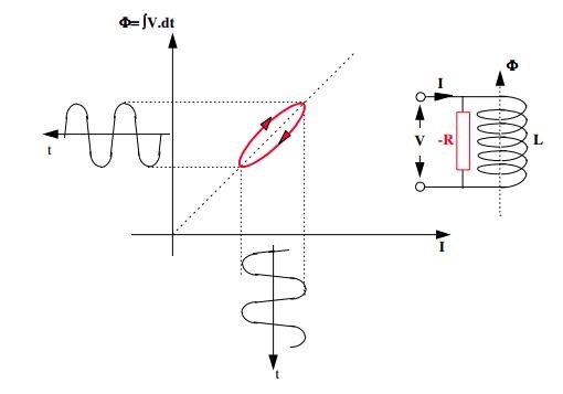
Figure 5. Φ v. I plot for negative resistor

Ref: PDF Document 'h2e' Image from 'A New Look at the Bearden MEG © Smudge, May 2014 Smudge', aka Cyril Smith.

Now, some of this makes sense to me, some of it, but not all of it. So I cant say this is how its done! I have researched working at the knee of the BH Curve before, but again, even though knowing about this area where there may be some advantage working, I can not say for sure this is what is required and what is needed.

2. Synthesizing a Clockwise Φ v. I Loop

It is known that, by the use of short-circuited coils, it is possible to divert flux from a magnetic material. Thus it may be possible to synthesize the clockwise loop by stitching together two different characteristics. Consider  the following typical Φ v. I characteristic for a saturating material.

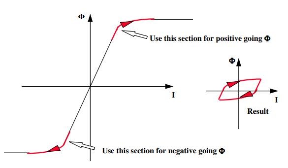
Figure 6. Φ v. I plot for saturating material

If we could arrange for flux within a coil to be positive-going while also going over the positive saturation knee, then when negative-going it does not trace its original steps, but passes over the negative saturation knee, we would get the combined characteristic we desire. The following section is devoted to this possibility. First consider a magnetic core having two coils connected in series aiding, yielding an inductance L.

Ref: A New Look at the Bearden MEG - By Ciryl Smith aka Smudge

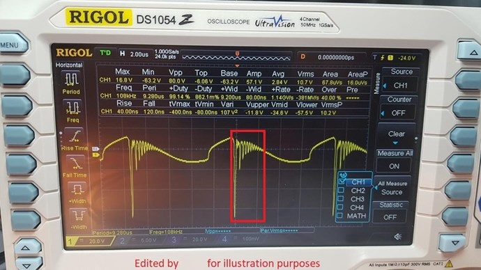
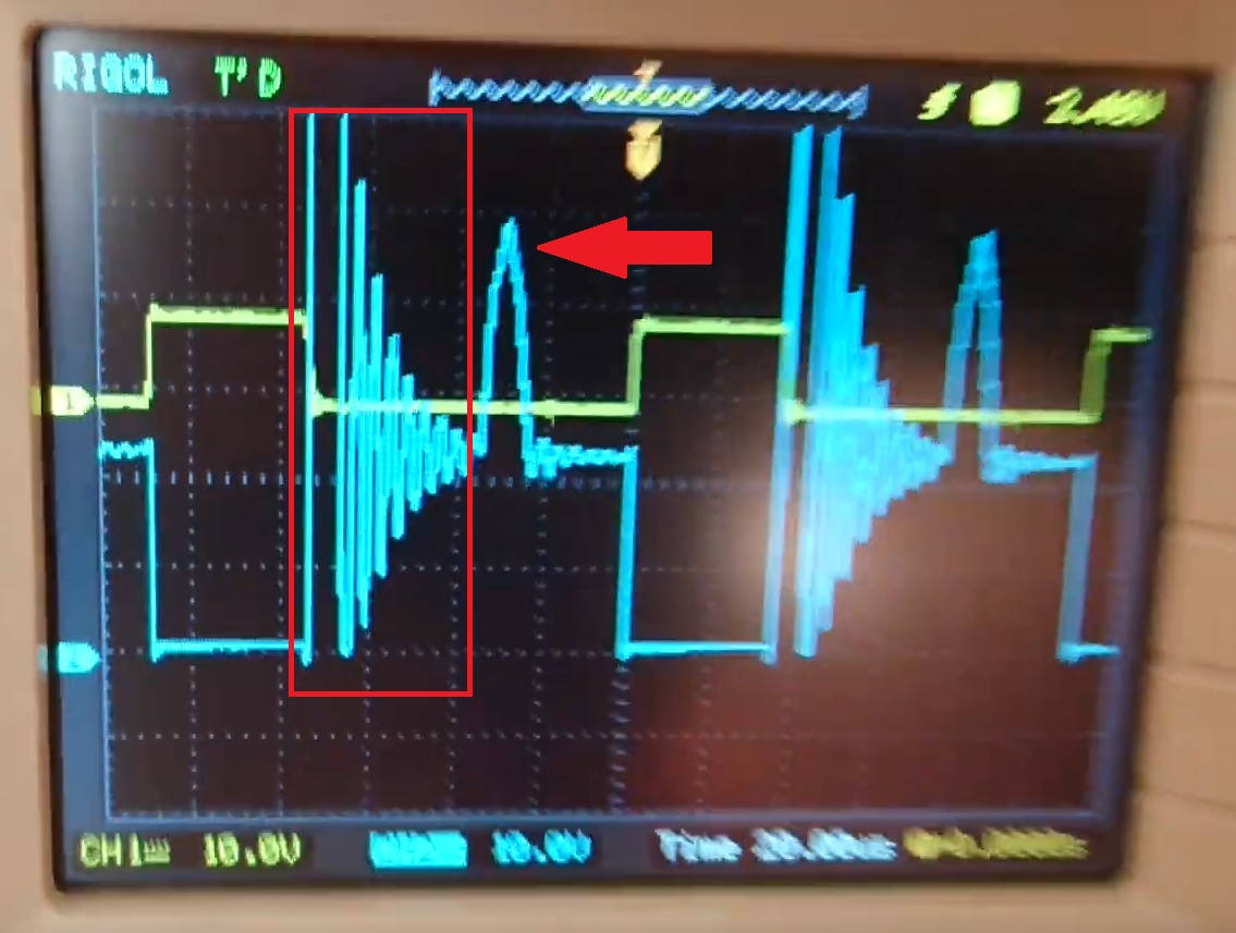
I would recommend more research in this area! In my following experiment, perhaps the loop here may have some relevance?


Cyril Smiths document: A New Look at the Bearden MEG, is attached below.

@YoElMiCrO - I also am looking forward to seeing more of your experiments and results! A greater overall understanding is what I strive for! I appreaciate your input here, Thank You! I found this interesting:

One way to cool a gas is as follows. First compress it isothermally. This means compress it in a vessel that isn’t insulated, and wait for the gas to lose any heat that is generated so that it returns to room temperature. Then insulate the vessel and allow the gas to expand adiabatically. We could call this cooling by adiabatic decompression.

You can cool a rubber band as follows. First stretch it isothermally. That means, stretch it slowly, so that it has lots of time to lose any heat that is generated. Then, suddenly destretch it, and before it has time to gain any heat from its surrounding, measure its temperature by immediately holding it up to your lips. You will find that it has cooled by adiabatic de-stretching. (If you stretch the band quickly (i.e. adiabatically) and immediately hold it up to your lips, you will find that it is hot. BUT ... before you try that experiment, close your eyes tightly. You don’t want the stretched elastic band to break and hit you in the eye. Believe me, you do not want that to happen.)

The method of adiabatic demagnetization has been used to obtain extremely low temperatures. A sample of a paramagnetic salt (such as cerium magnesium nitrate), already cooled to low temperatures by other means, is magnetized isothermally. The sample is often suspended in an atmosphere of helium, which can conduct away any heat that is produced, and hence keeps the process isothermal. It is then insulated (by pumping out the helium) and suddenly and adiabatically demagnetized. This process of isothermal magnetization followed by adiabatic demagnetization can be repeated over and over again. Temperatures close to 0 K have been reached in this manner. You could actually reach a temperature of absolute zero if you did this an infinite number of times – but not for any fewer.

In the analysis that follows, I shall have to assume that you are familiar with the concepts of B, H, magnetic moment and magnetization from electricity and magnetism. 

In brief, the magnetic dipole moment pm of a sample is the maximum torque it experiences in unit field B. That is, the torque is given by . τ = pm × B The magnetization M of a specimen is defined by ). ( B = µH = µ0 H + M The magnetization is also equal to the magnetic moment per unit volume. 

Now consider the following.

If the tension in an elastic string is F, the work done on the string when its length is increased by dx is F dx.
If the pressure of a gas is P, the work done on the gas when its volume is increased by dV is −P dV.

Ref: http://astrowww.phys.uvic.ca/~tatum/thermod/thermod15.pdf

Again, I just want to say, do your own research here, I agree with what YoElMiCrO has said, I am partly in agreeance with some of the above, but not all of it! Come to your own educated conclusions!

Stay safe and well everyone!

Attached Files

  • Liked by
  • Inception
  • Shadow_
Fighter posted this 29 April 2020

For later references I'm quoting YoElMiCrO's analysis about ZPM from here:

Hello everyone.

In order not to distort the Fighter tread, here is this observation.
The Fighter ZPM even though it looks like the document published by N.E. Zaev.,
does not fully share what is published, as it is not exact.
In your case the potential energy is higher by using bucking coils, good
that idea on his part.
In his tread I will talk about what happens from my point of view.
But let's see in practice what Zaev talks about.
This scope image shows what it is based on…

And this is the circuit in question ...

If we look at the mauve stroke, it is Ton's pulse at the gate of the mosfet and the
yellow stroke is the behavior in the drain of the same.
Your system works in the revercible area of ​​hysteresis, not in the
saturation area as we are studying.
That is why your system exchanges heat with the medium.
Let's carry out an analysis by simple inspection ...
The resistor parallel to the primary is powered by the source for
the voltage drop time at the mosfet drain, the latter being
of the order of the ns, after turning off the mosfet the resistor remains
powered during the adiabatic response time of the core.
So in theory TD>>TM and the energy gain is proportional
a TD/Tr> 1.
I hope this post will definitely serve the concept in which
your system is based.

Thank you all in advance.

YoElMiCrO.

Note: YoElMiCrO, thank you and you're really welcome to post your thoughts here, it's about ZPM so it's not a problem and no distortion 🙂

"If you want to find the secrets of the universe, think in terms of energy, frequency and vibration."
Nikola Tesla
  • Liked by
  • Inception
  • Shadow_
UndisclosedMember posted this 29 April 2020

@Fighter, and all,

I agree, this is important! If you think a post by anyone is important to your work, please do as Fighter has, re reference it and quote that post in your thread! This is excellent technique for referencing material that is important to your thread!

Great Work Team! I am so awesomely Proud of our Progress!

Floyd Sweet said:

With regards to over-unity phenomena it is important to note that so long as positive energy is present in a positive / flowing time regime, unity and over-unity power gains are not possible. The summation of the losses due to resistance, impedance, friction, magnetic hysteresis and Eddy currents and windage losses of rotating machinery will always reduce overall efficiency below unity for a closed system.

Floyd told us he did not use Hysteresis as such, reading between the lines that is.

Attached Files

  • Liked by
  • Inception
  • Shadow_
Fighter posted this 30 April 2020

And another piece of information related to ZPM as a quote this time wrote by Vidura here:

If I may add my two cent's regarding yoelmicros post about the effect described by N.Zaev: Time ago I did the experiment and noted that with a puls as short as 200ns applied to a inductor it becomes "spontaneously magnetized" that means before a current is actually flowing thru the inductor. but the following demagnetization is about five times longer, and with active power flowing thru a resistor load. The energy returned in form of the BEMF is clearly greater than that from the applied pulse. Practically it is not very useful, as the gain is very low, and it depending on the mass of the core. But it seems that in the case of the ZPM it is notably magnified by the cancelling coils, which would make the effect strong enough for practical implementations. 

Thank you all for the great work.

Vidura

@Cd_Sharp, this could be a key useful for your research about enhancing the coils for your device: "with a pulse as short as 200ns applied to a inductor it becomes "spontaneously magnetized" that means before a current is actually flowing thru the inductor. but the following demagnetization is about five times longer, and with active power flowing thru a resistor load."

"If you want to find the secrets of the universe, think in terms of energy, frequency and vibration."
Nikola Tesla
  • Liked by
  • Inception
  • Shadow_
YoElMiCrO posted this 30 April 2020

Hello everyone.

@Fighter.

This is a preliminary analysis that I have done on your ZPM
long ago I think in your case when using Bucking-Coils
is based more on the nonlinearity of the inductances even than
also uses the phenomenon described by N.E. Zaev. let's say
which is a conglomerate of phenomena not so studied.
Thanks to your ZPM and your observations I began to study
or at least try to understand what the real phenomenon is not
so observable that it transcends the physics we know.
It is this subtle phenomenon that really involves everyone
the devices whose creators claim AU, still under study.
This is my view point…
On your device, during the magnetization cycle the inductance
magnetizing is the difference between them since the fields
magnetics are in the opposite direction, that's logical!
However during the demagnetization cycle the inductance
grows due to their attempt to maintain a sense of
current circulation, this image I think will clarify what I say ...

As the magnetizing current is common, the energy grows by itself
because now the inductance is greater than the initial one and its COP will be proportional
to the difference between them.
This is demonstrated by the time it takes to return to Edc during
the BEMF, since for the core to return to the initial position
within the hysteresis cycle it will have to be fulfilled that (EdcTon)=(BemfToff).
This idea of ​​using Bucking-Coils started WET, now
parked due to time/work problems, also Vidura's post
here and other experiments related to another phenomenon you notice.
Here I leave you an image with some theoretical approaches in case
It serves you something, if it helps you do not hesitate to ask.

Thank you all in advance.

YoElMiCrO.

  • Liked by
  • Inception
  • AlteredUnity
Fighter posted this 30 April 2020

Thank you YoElMiCrO, I will need some time to process this information. You're welcome anytime to post in this thread.

"If you want to find the secrets of the universe, think in terms of energy, frequency and vibration."
Nikola Tesla
  • Liked by
  • Inception
Atti posted this 30 April 2020

Hi.

I need a little help.
I’ve done a similar test before, so I’m putting it in this thread. Seeing here in this thread the work of Fighter Vidura and Yo. Chris and CD's layout also fits here, I think.
The two tests are measured at the fet gate and at the light bulb load, respectively. Looking at the times entered and withdrawn. As well as the effect of the loosely coupled coil on the primary. (that would have been the essence of the past video)  At 1:40 a slow diode is displayed. So you can actually count on the delay.
  Schematic drawing at the beginning of the video. I'm not sure I'm going in the right direction. What are your opinions?

Fighter posted this 30 April 2020

Hi Atti, the layout looks more like a layout tested by @Cd_Sharp. Is the input coil wrapped over the output coil and they are bucking coils ? I just started to test ZPM with a third coil separated as input so my experience on this kind of configurations is limited. But I see a interesting thing, consumption from source is jumping a bit but then returning to the previous value when you add the second light bulb. And also I see something which I'm very familiar with and it's a part of ZPM's specific pattern, the signal of a coil is looking like a spring.

The quote below is part of a previous post made by UndisclosedMember in this thread here:

The Interactions between the Coils.

In Fighters ZPM we see a very interesting Spike:

Marked in Red is the process I describe above in the video. The Coils are like a spring, and Act and React together in Magnetic Resonance. This is an Electromagnetic Induction dance, or disco. Electrons are getting some moves on and the Disco is going off...

This is excess Electromagnetic Induction after the fact! After the Input has excited the Coils into this Resonance.

In my opinion you're going in the right direction and you also have another interesting effect: consumption from source is jumping a bit but then returning to the previous value when you add the second light bulb.

I took a screenshot from your video and marked the spring-like pattern and also something else, a additional spike is present even if your input is not changing. That's intriguing...

Guys you may post your opinions here, it's not a problem.

"If you want to find the secrets of the universe, think in terms of energy, frequency and vibration."
Nikola Tesla
Atti posted this 01 May 2020

Hey Fighter.
The layout, so the coils of the drawing is connected.
-The spring-like pattern is due to the AMCC core.
Other transformers do not have such a spring-like pattern (e.g. hypersil)
-The additional pin is only present if only the loosely coupled coil is connected (according to the drawing there is only a light bulb on the right coil, in which case there is no light bulb on the coil on the left)
However, this is also only with one kind of diode! (This is a very old diode. Tungsram SY100 but unfortunately I can't find a datasheet about it. But I assume it can be very slow)
-I also tried with another transformer at a lower frequency.
The effect is the same.

-This load raises the Fet Drain voltage. If it is very high and of inadequate value then Fet will be ruined!!

Atti.

Close