Spatial Energy Coherence circuit

  • 4.7K Views
  • Last Post 11 July 2023
  • Topic Is Solved
Jagau posted this 14 February 2023

Hiall

This thread will be dedicated to an inventor who left us a lot of information on "Spatial Energy Coherence" commonly called "SEC"

This circuit connects to the sea of energy that surrounds us by opening a door with it. Building different circuits will teach us more and how to do it.
Thank you Dr. Ronald Stiffler.
Jagau

editor posted this 24 April 2023

All good, tnx.

br, e

Fighter posted this 25 April 2023

Quoting:Jagau

I'm replicating Dr.'s early experiments while trying to figure out the whole technique behind this. So step by step my first attempts lead me to believe that I still have to learn this technique, I don't want to skip any steps and I start with his first experiences in order to grasp the meaning. 

He didn't say everything, you have to be well immersed in his technique to understand, but fortunately he left us a lot of information on the web and shared several experiences.

I understand, learning and understanding device's behavior. That's what I did with ZPM too in early phases, burned many MOSFETS during that learning process... šŸ™‚

One thing is not clear to me, shouldn't the coils be oriented 90 degrees to each other in 3D space so they cancel their mutual inductances ? Or that configuration is specific only to later devices ?

Thanks,

Fighter

"If you want to find the secrets of the universe, think in terms of energy, frequency and vibration."
Nikola Tesla
Jagau posted this 25 April 2023

Hi Fighter

In fact in his first experiences and for this type of configuration he does not yet speak of coils at right angles but one on top of the other, like the photos provided above, I try to understand his progress since the very beginning of his experiences.
Later in more advanced configurations as I had shown at the beginning of the thread, without using a signal generator but using a negative resistance oscillator with an NPN so in these configs he speaks of coils at right angles to one with respect to the other. I hope that helps for now.

Jagau

Fighter posted this 25 April 2023

Yes, thanks for the clarification.

Fighter

"If you want to find the secrets of the universe, think in terms of energy, frequency and vibration."
Nikola Tesla
Jagau posted this 25 April 2023

First observations:

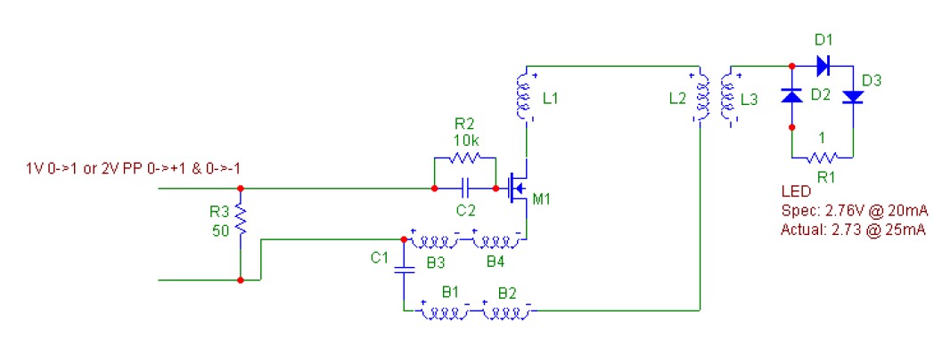
In this first experiment, two coils are pulsed with a signal generator with a sinusoidal output producing 3 power peaks at 4mhz, 11mhz and 24Mhz. The LED lights up at 2.6 Vdc with a current of 30 ma measured on the oscilloscope.

The negative output of the generator signal is not connected only the positive, as well as the coils L2 and L3 only one side opposite to the other is used, as in the schematic.

The circuit is extremely sensitive when objects approach it, it stops completely if touched with the fingers.

The configuration with one avramenko plug, two diodes and one LED, with a single wire power supply produces an effect that has already been proven in other types of circuits and does not draw additional power from the source wth LED ON or OFF.


Jagau

editor posted this 25 April 2023

Hi Jagau!

Since this is one wire transfer did you try multiple (2-3) devices connected to the FG?


br,e 

Jagau posted this 25 April 2023

For the moment i used just one device as you see in photo.

It is not an energy transfer, it is a localized communication which uses the local ambient energy which is located between a generator and a receiver (circuit). 

There is no energy transfer between the generator and the circuit. The generator just varies the frequency using just one wire, the circuit excite and communicates with the energy that is all around the circuit (ambient)

That's how I understand it at the moment.

The consumption of the generator is as if it were in stand by, I added up to 5 LEDs to the AV plug output without any changing at the input.


Jagau

editor posted this 25 April 2023

Hi Jagau,

understand, thanks for the explanation.

For sure i will try to replicate it in the coming days.


br, e

Jagau posted this 26 April 2023

An LED needs 55 milliwatts to light normally. For a test at the output of the signal generator without the circuit, when i load with 50 ohm resistor at the output of S.G., check with my oscilloscope at 15 Mhz only 40 milliwatts (1.62 v x 24.69 ma) are harvested ( when the 2 wires of the S.G. are connected and 0 watts when ground is not connected on the load.

In a second test with the circuit, I added to the circuit a series resistance of 75,000 ohms just before the two diodes of AV plug in order to check if the S.G. entered in any way and with the law of ohm if we calculate the current which could pass there we would have I= E/R 1.64 V / 75000 = 0.000022 amp or 22 ua.
It is therefore impossible for an LED to light with so little current and yet it lights very well. The contribution of the ambient environment has something to do with it, I'm now quite certain of it.

Jagau


Jagau posted this 29 April 2023

I am currently trying to reproduce this experience, re-read the title twice!

A more advanced approach.
Requires no power supply as power is derived by special phasing and access to the Spatial Energy Lattice.


Circuit Comments
B1,B2,B3 & B4 with C1 form a delay line.
Removal of C1 will stop circuit operation and extinguish the LED.
Replacing C1 with a wire will reduce the LED output to barely visible or extinguished.
Removal of B1,B2,B2 & B4 and C1 and replacing with a short wire will extinguish the LED.

You can read the spec of the Led are 2.76v and 20ma and he get 2.73v and 25ma with1 volts input.

Jagau


Close