Jagau
posted this
15 February 2023
- Last Edited 15 February 2023
Hi Atti
These are very good questions you ask, according to my first try and what I observed following the recommendations of the inventor friendly called the DOC;
About your questions;
-Is it necessary to loosely couple the inductors?
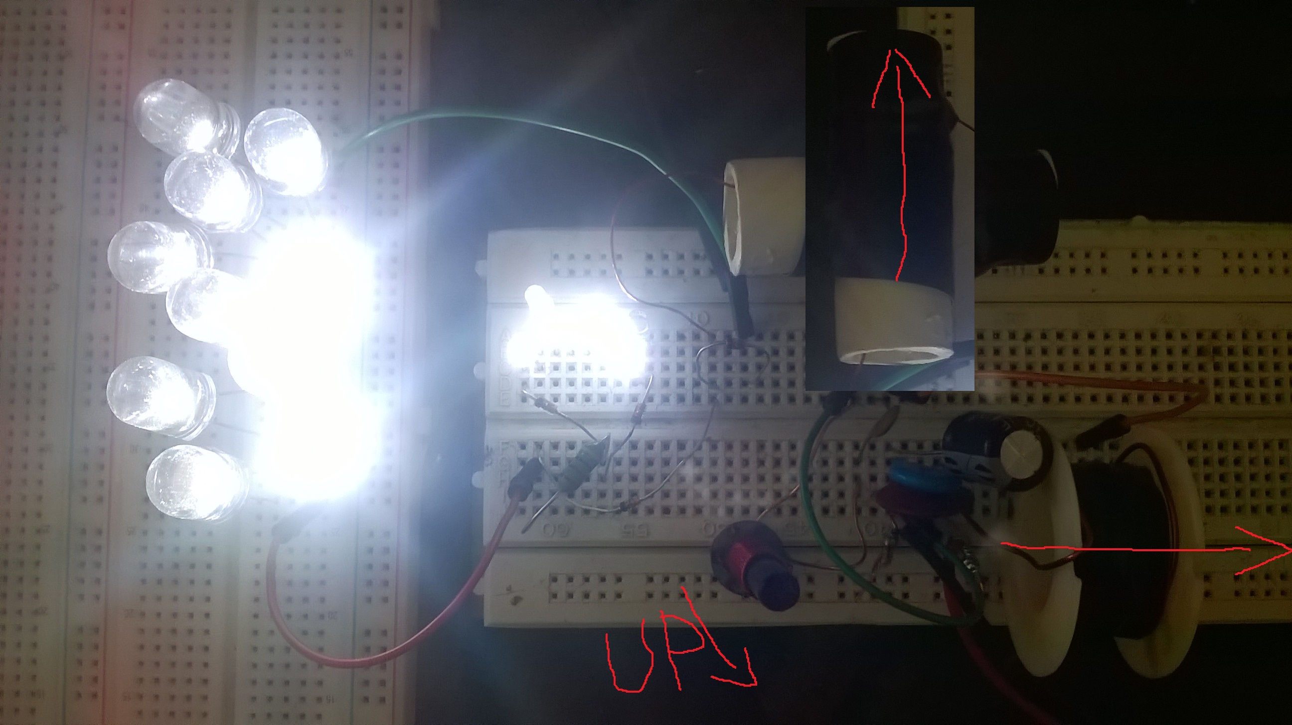
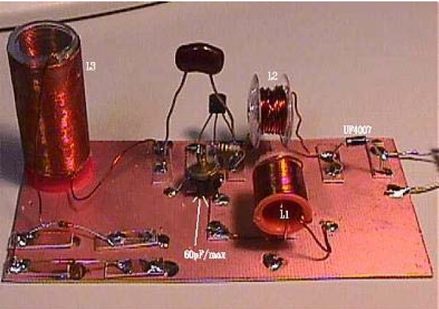
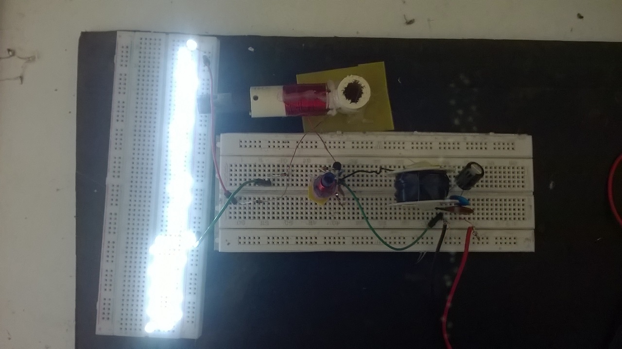
The 3 coils must, for better performance, be at 90 degrees relative to each other in a 3 dimmension plane, thereby canceling the mutual inductance between each of the coils
-What happens if the connection is tight?
The connections between the components must be as short as possible given our extended frequency up to 500 Mhz
-Can the resonance points come from an external factor? For example, is the "primary" vibration circuit separate and the "secondary" vibration circuit separate?
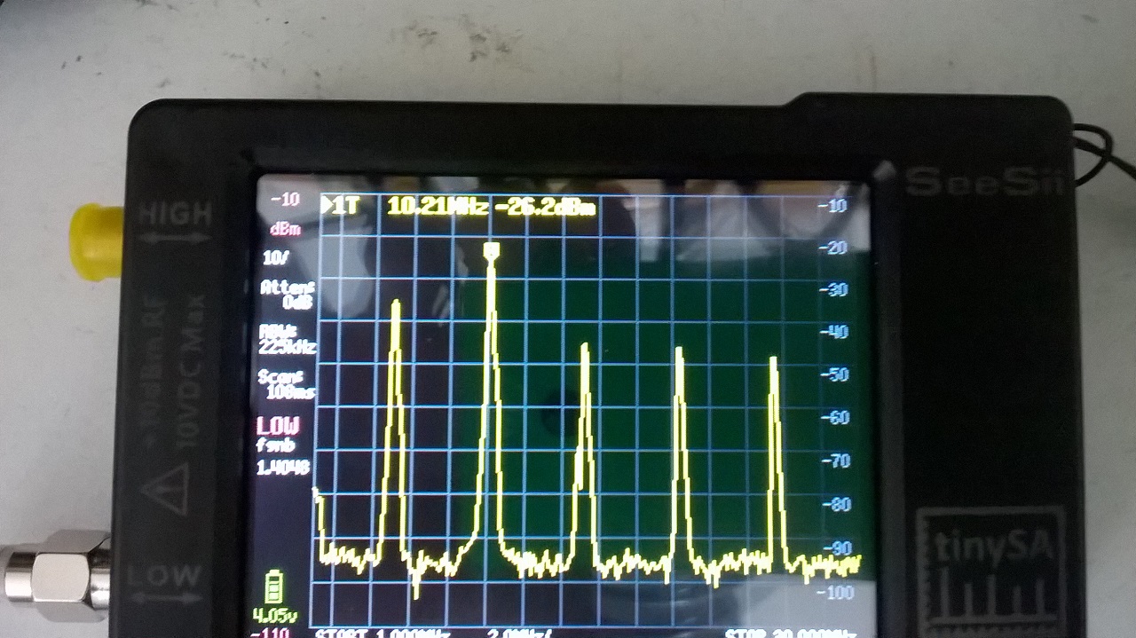
L1-c1 establishes the frequency of use and I admit that my experiments at this stage are primitive but given that what I understand for the moment the coherence (Wiki makes a good definition of it) and the fact that this circuit operates in very high impedance any nearby object or mass, even our hand, disturbs its behavior.
https://en.wikipedia.org/wiki/Coherence_(physics)
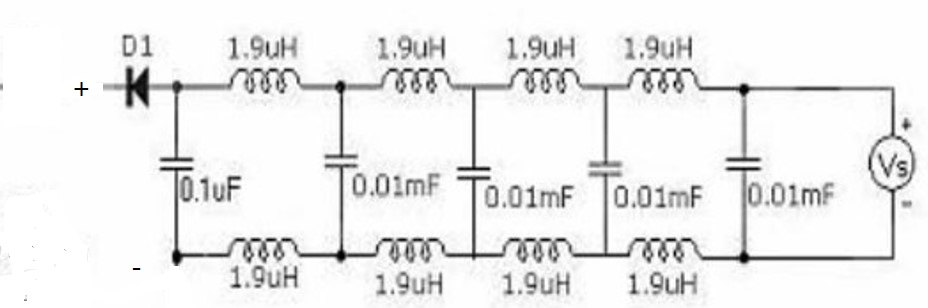
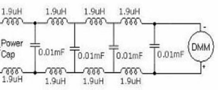
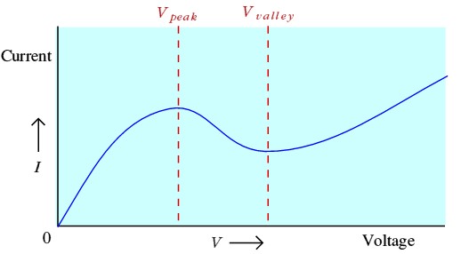
The coherence resonance is established between L2-L3 and the internal capacitance of the circuit, in addition to the Self resonance of the coils and when the BJT enters the negative region, a pumping effect of the energy of the environment occurs. Negative region is between Vpeak and Vvalley
But as you can see, this type of experience is the one I've been looking for for a long time because I firmly believe that the energy around us is available.
I hope that answers your questions if there is anything else let me know.
Jagau
What we consider to be empty space is merely a manifestation of unawakened matter. N.T.