Atti
posted this
24 March 2023
Hi everyone.
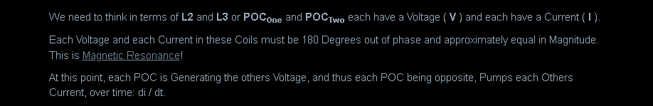
does anyone understand why and could explain how a repetitively DC pulsed coil assembly adheres to resonance, when the purpose of the pulses in a 3 coil assembly is to regauge the potential on the POCs to make them self-act through mutual action during offtime?
This is just my opinion. You don't have to agree with it.
Obviously only the person who came up with the original concept (if credible) can explain it properly, but since there are similarities from other people's work done years ago, I'll just refer you to what the light years ahead of you Sensei says.
( The work of others,or their implementation should not be addressed at this moment. )
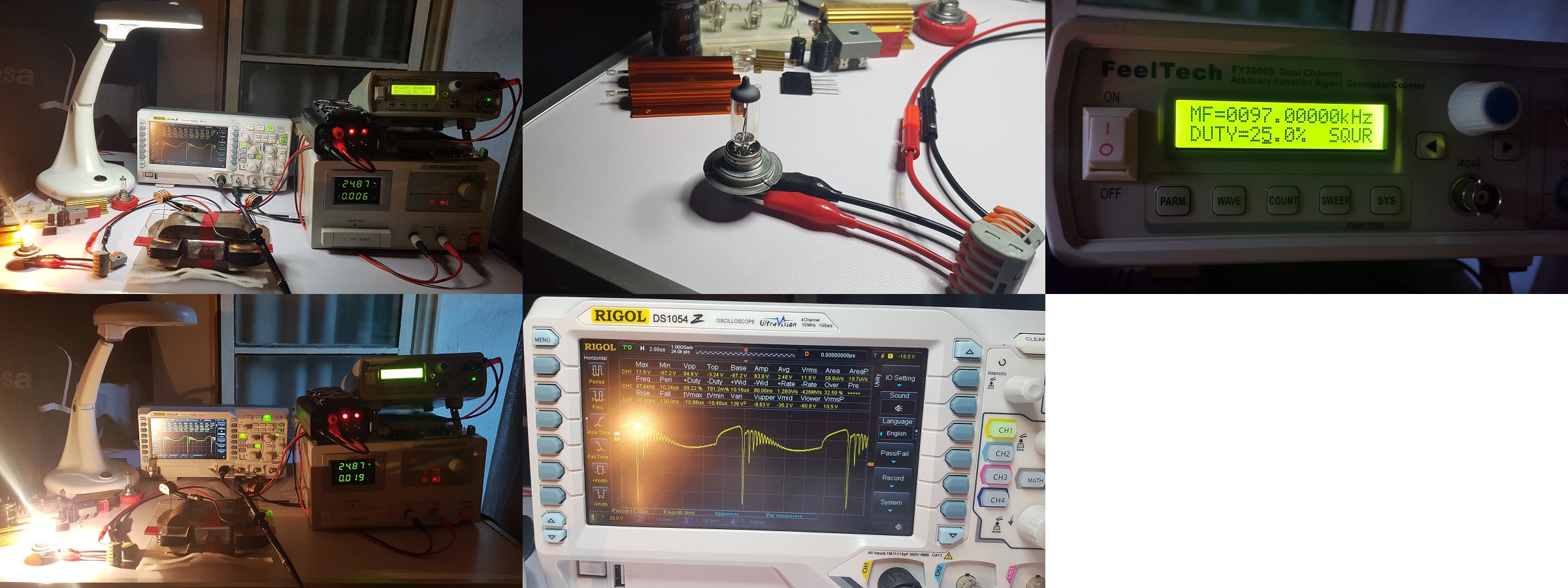
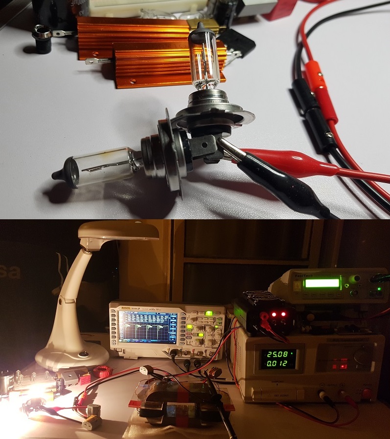
The original implementations,measurements cannot be relied upon because they have not been shown to anyone by Sensei. There is no public measurement data. No public operational video recordings. No public blueprints. Just some video footage that misleads. Just a few effects that suggest the alleged operation. It's because it covers everything in theory but misses the point. If an inventor really wants to change the fate of the world, he should communicate it in a way that everyone can understand. He doesn't use words to prove his greatness as an inventor, but he has no material product. An oscilloscope picture proves nothing. That is why your claim is not credible. If L2-L3 helps the performance of L1, it does not mean that we have excess power. Just because the input current is reduced does not mean anything.
Many have tried the reconstruction. Why only the master succeeds. Isn't it strange?
But let's focus on the facts.
Let's look at the questions, the answers. Quote:
Why I do what I do is obviously known only to me (but it's no secret, Árpád Bóday's magnetodynamic machine)
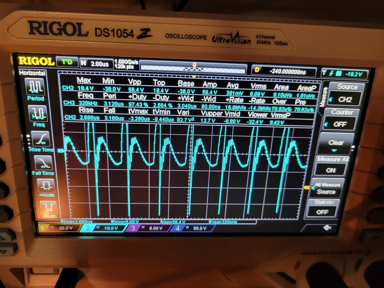
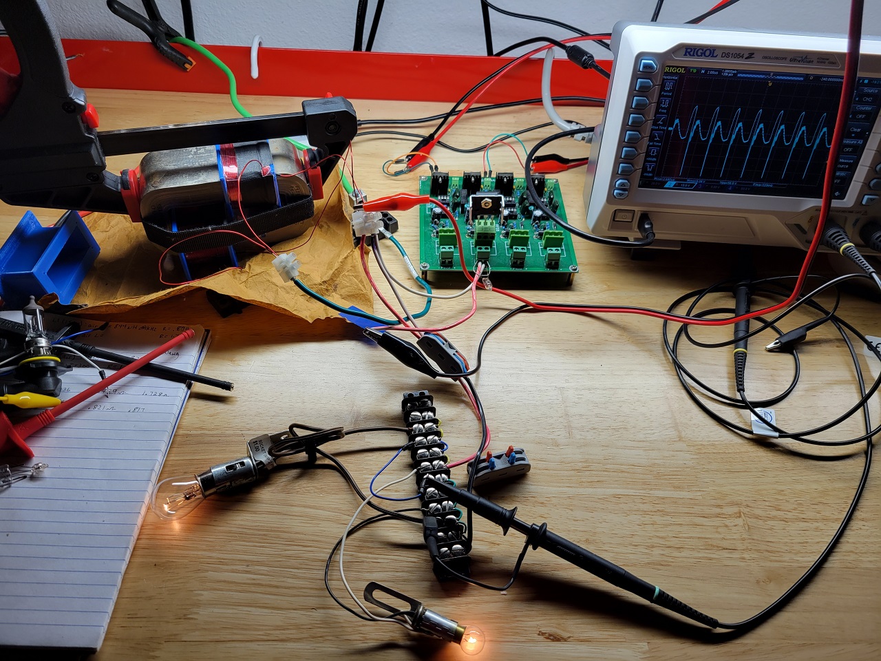
Ok. 180° deviation. You can see it here:
But what do we see?
The left primary coil is getting a square wave signal. With a series capacitor on a series resonance. The loose coupling of the right coil causes a slight time delay.
(loosely coupled and that's important. Similar to the implementation of the sensei. But don't tell the Sensei! )
By putting the right parameters together, the phase relationship of the right and left inductors can affect the two inductors in the middle. The two inductors in the middle are connected opposite each other. So under conventional excitation conditions, there can be no induced voltage in them. The two coils in the middle would replace the inductance L2-L3. At a suitable resonance point, it can be seen that a voltage is excited between the two points. Since this is a barren design, the current drawn from the power supply at the resonance point is reduced by sense. So is this free energy?
I would like to see practical implementations by others. It could be the ZPM.
( leave the theory for later)
Atti.