Editor's ZPM replication

  • 4.3K Views
  • Last Post 29 June 2023
editor posted this 07 November 2022

Hello All!

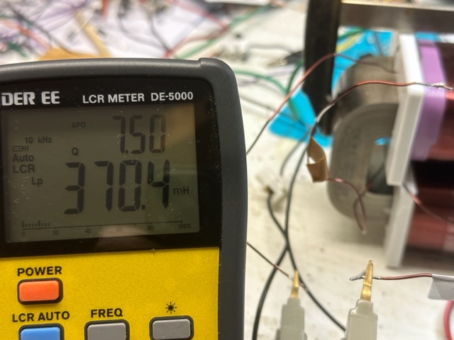
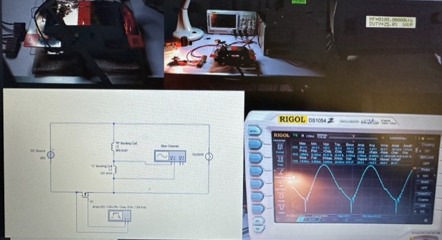
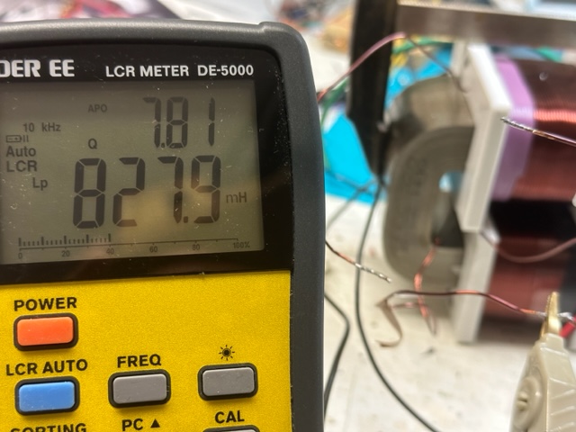
I was in touch with the Fighter and now I decide to show what is going on and to get some new ideas on how to get the signal that we all expect. Below is a quick video showing the simple setup. The coils are 1mm L1 cw 210T (370mH), L2 280T ( 828mH). 


The poles were tested with the phone app named Pole detector, works ok.

I have built some other coils too, with different turn numbers but the output was almost the same.

I have 2 different grounds to play with. I did use the regular power supply but my home appliances were not happy at all, so I decided to isolate everything.

For sure there are differences from Fighter setup, like the core, the position of the coils, the voltage, not sure about the ground.

the video:😁


bre


editor posted this 31 December 2022

Hi CD_sharp

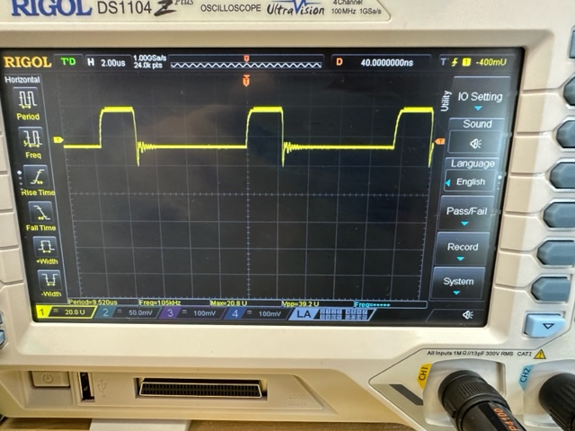
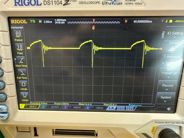
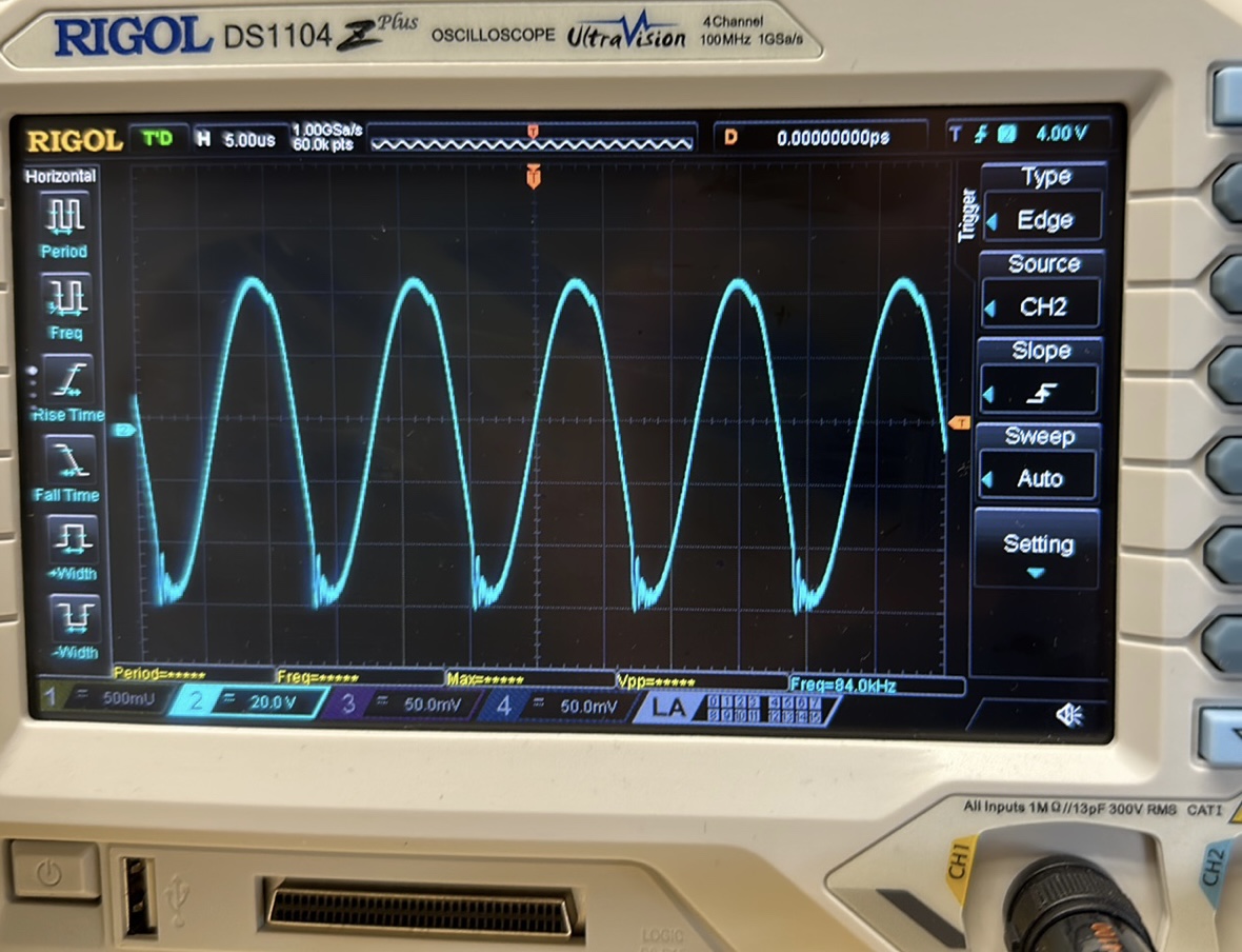
Thanks for the tip, I did try what you suggested, Isolated the scope, and ground the negative of the PS. Try 2 different PS, using the grid and the battery with the inverter. Still working like a dimer. The two photos represent just the difference in load 5w vs. 50w.


br, e


Atti posted this 31 December 2022

Hi everyone.

@editor.
Notice the difference between the two pictures. In your case, 5w-50w.
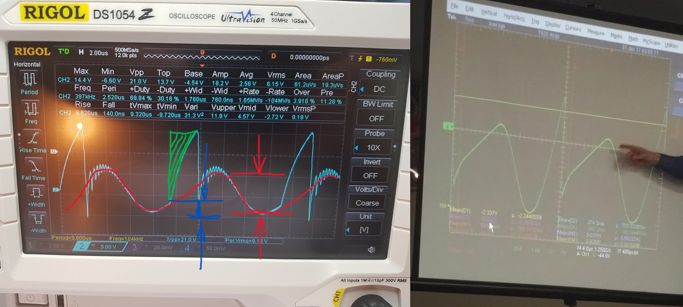
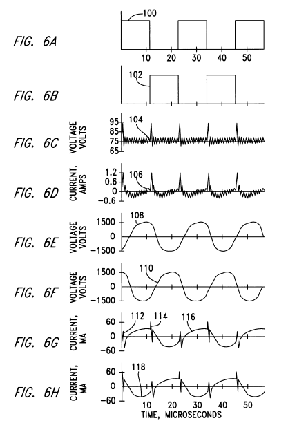
Let's look at Fighter's picture.


You can see the negative spike.
- Blue marked area.
It depends on the rate of current change and the size of the load.
- Green marked area.
The greater the magnitude of the load, the larger this area.
(Rounds the edge of the square sign.)
-Red marked area.
That's what's interesting about it all. In my opinion, the magnitude of this depends on the parasitic capacitance.
If it is capacity, then it is resonance.
Let's look at J.L.Naudin's diagram, or the patent diagram.
If the driving pulse is a square, then how will the voltage on the secondary side be sinusoidal?

If I place a neon lamp at the connection point of the two coils, it will light up according to the parameters. It gets stronger as the frequency increases. Since the circle wants to close somewhere, it chooses the shortest path. And this is grounding.

However, it doesn't matter where I put it!

  Sometimes the power taken from the network increases and sometimes it decreases. Frequency, duty factor and supply voltage dependent.

I did a quick scan.
Full reproduction will not be easy.
Wire the coils based on the parameters already specified.
So 150 and 300 threads.
(actually, 2X150 and 60 threads on each column due to a later test)
I was just testing in this setting, currently the current is not close to zero.
I'm just setting the frequency here. The filling is 20-25%.
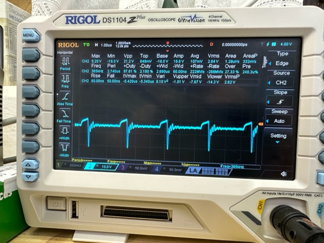
You can see the several resonant members in the breaks.


Equally...


Atti.

editor posted this 31 December 2022

Hello Atti!

Nice build you have there. I'm not sure what exactly you are recommending, but
I will for sure try to tune it again.😀


have a nice night or day, e

cd_sharp posted this 01 January 2023

Editor, Atti suggested you wind 150 and 300 turns. I'd say any setup is worth trying as long as you keep the 1:2 turns ratio. Other turn ratios can be used, but 1:2 is the basic. Stay strong!

If you know how to build such a device and you're not sharing, you're a schmuck! - Graham Gunderson

editor posted this 01 January 2023

Since I'm running out of options, I will try the 150/300 ratio.

Thanks for the tip, and happy xmas to all!🥳


have a nice day or night, e

editor posted this 04 January 2023

Hi All!

Make the reduction on turns, so 150/300. Currently I'm reading Fighter's ( Romanian ZPE) theme to figure out what I'm missing. Did some experiments with the grounding, since I have all the possibilities, no special results. Then i starter with

Smoller coil, let's say I'm close,but missing the spike. See for yourself. Will keep going.


br, e

cd_sharp posted this 04 January 2023

Guys,

I need to make an observation. Since the negative terminal of the power supply is connected to the ground and the oscilloscope negative terminal of the probe is also connected to ground, but they are not sharing the same circuit connection, there is a short circuit situation.

I advice doing a differential measurement instead. That would plot a trace that is colser to the reality.

Stay strong!

If you know how to build such a device and you're not sharing, you're a schmuck! - Graham Gunderson

editor posted this 05 January 2023

Hi Cd_sharp

The oscilloscope is grounded, the PS is not grounded, and on the isolated transformer. I even use the inverter or just batteries. No difference...

Even if I change the grounding, the negati of the PS is grounded, but the oscilloscope is not grounded. 


this is the closest that i got yesterday.


br, e

cd_sharp posted this 05 January 2023

the PS is not grounded

That explains why you're not seeing results. The schema needs to be updated as it can mislead other people. Please, connect your PS negative terminal to ground and retry!

I believe the device can also be scaled up by moving the coils to use the space optimally. If I only had a ground connection..

Stay strong!

If you know how to build such a device and you're not sharing, you're a schmuck! - Graham Gunderson

Atti posted this 06 January 2023

@editor.

Hi.

The oscilloscope is grounded, the PS is not grounded, and on the isolated transformer. I even use the inverter or just batteries. No difference...


Watch it again from 0:40.

In my opinion, one possible problem is with the mosfet gate driver.
Check again who are the members who reproduced the ZPM device and what controls they used.

I tried the following mosfet drivers.
(because if the drive of the mosfet gate is not perfect, it can get very hot. It is not certain that perfect operation is the right solution!)

-when the TL 494 output is simply controlled -IRFP260 mosfet.
- when only the output of the TL 494 controls a high-current transistor.
-SG 2535-IR2110-IRF540n
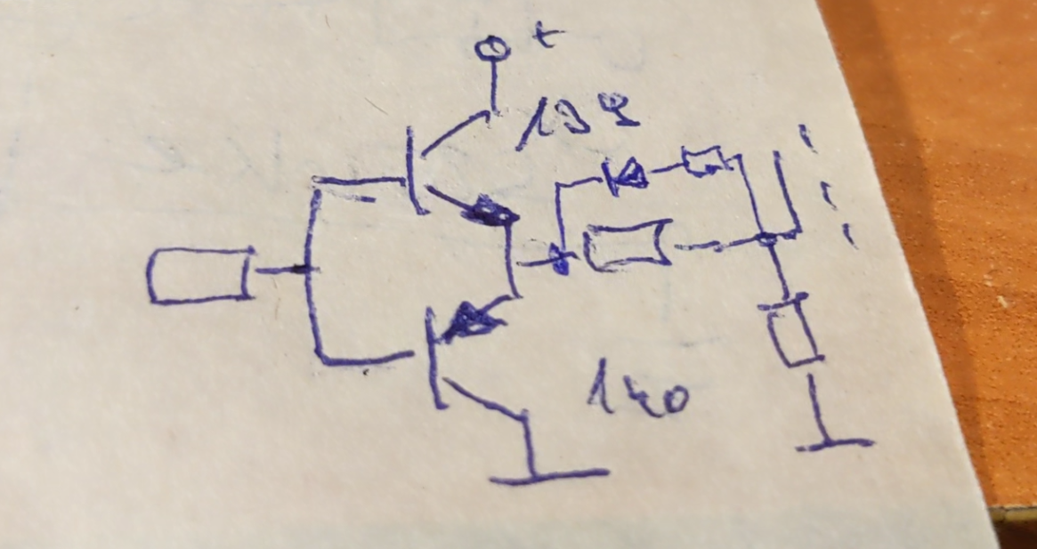
- the TL494 controls a gate driver, this is a BD 139-BD140 -IRFP260 mosfet

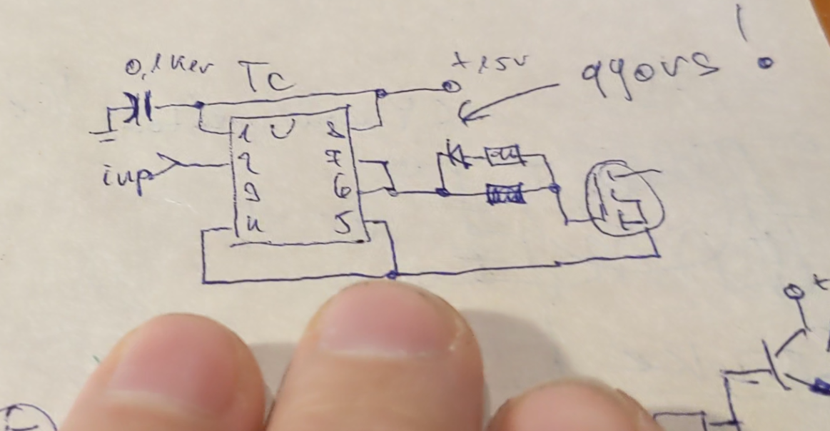
-TL494 drives a dedicated driver TC4429 -IRFP260 mosfet
The transistor is slow. Therefore, there is no proper spike.
The speed of the gate drives has a big influence. It does not allow swings. Furthermore, there is no external excitation. You can see it here:
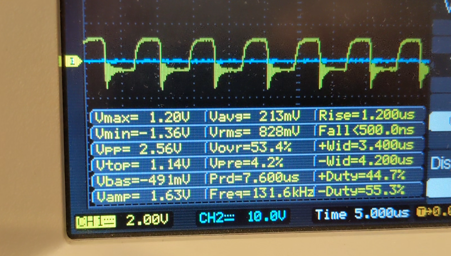

The mosfet does not heat up at all!

So I conclude that driving the mosfet gate requires a swing time. If this is present and combined with the parasitic capacitance, resonance can occur. The presence of the negative spike (positive current) also heats the mosfet.

-Furthermore, it is questionable why Fighter's mosfe got so hot. Why does it have to be cooled to such an extent?
This could be a sign of operation.

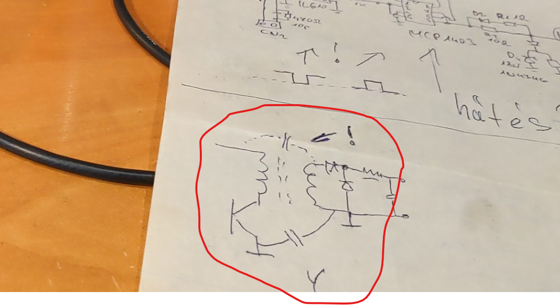
And one more thing. Don't forget the importance of parasitic capacitances either.
 

Atti.
Close