Editor's ZPM Replication

  • 2.7K Views
  • Last Post 30 January 2023
editor posted this 07 November 2022

Hello All!

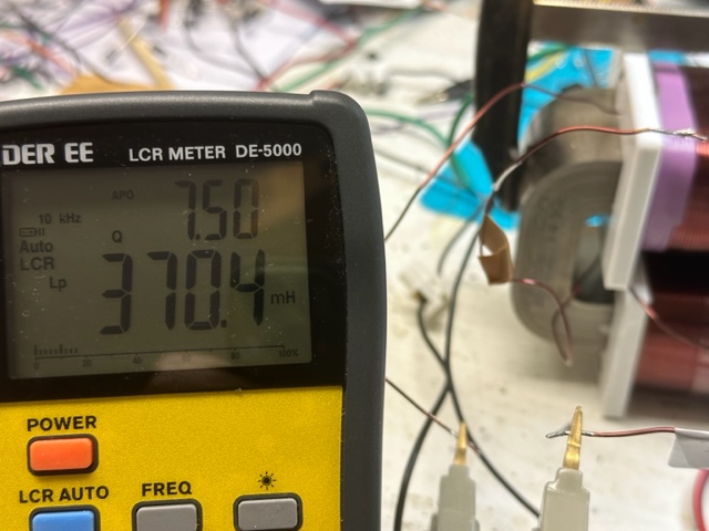
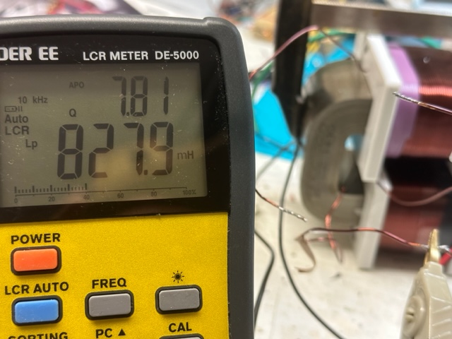
I was in touch with the Fighter and now I decide to show what is going on and to get some new ideas on how to get the signal that we all expect. Below is a quick video showing the simple setup. The coils are 1mm L1 cw 210T (370mH), L2 280T ( 828mH). 


The poles were tested with the phone app named Pole detector, works ok.

I have built some other coils too, with different turn numbers but the output was almost the same.

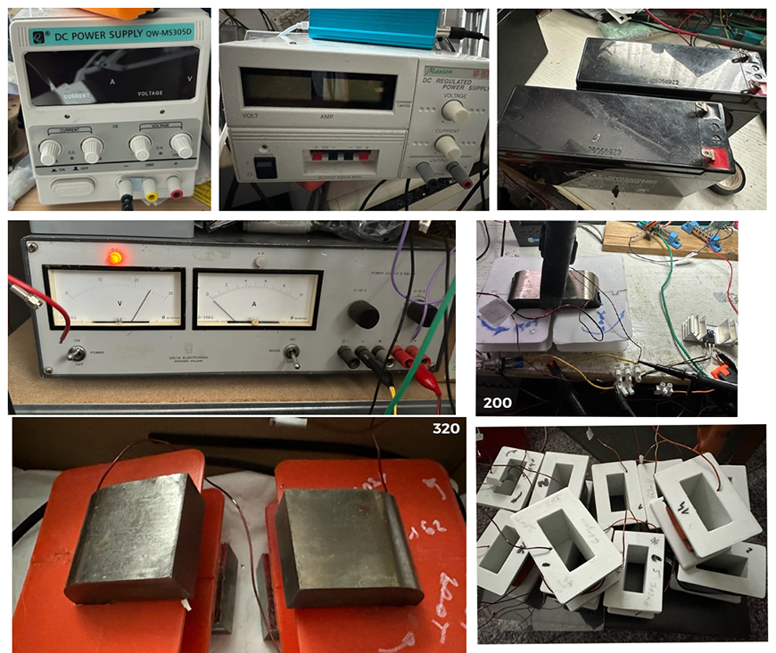
I have 2 different grounds to play with. I did use the regular power supply but my home appliances were not happy at all, so I decided to isolate everything.

For sure there are differences from Fighter setup, like the core, the position of the coils, the voltage, not sure about the ground.

the video:😁


bre


editor posted this 14 January 2023

Hi everybody!

Spend some time in the lab after a short pause, with no major progress.
Checking the data for the core AMCC320 I noticed the orientation info, for the 
first time. I was asking myself in the past what the meaning of the markings on the core was. So for my core the orientation is North. Maybe somebody did some experiments on what happens if you put the core together the opposite way. Is it possible to damage the core in some way or the polarization? Or the more straightforward question, is it possible to destroy the core?


have a nice day or night, e

Fighter posted this 14 January 2023

Hi Editor,

The orientation is related to how the core was cut in two pieces.

When the orientation signs are used that means the gap between the two pieces is minimal and the surfaces where the pieces are attached to each other are matching to each other.

When the orientation signs are not used that means there are higher chances to have a bigger gap when the pieces are attached to each other.

No, I don't think that not using the orientation signs could destroy the core but most probably you'll have a bigger gap and that would temporary modify the core's characteristics and they'll not match the core's specs anymore. It will not work as in specs. Just temporay until the cores are attached together again using the orientation signs.

I always used the orientation signs, never tried to use them the other way.

Regards,

Fighter

"If you want to find the secrets of the universe, think in terms of energy, frequency and vibration."
Nikola Tesla
Jagau posted this 14 January 2023

Hi editor
Just to confirm what Fighter told you and when I received my AMCC320 there was a note in the box telling me that aligning the color lines in the center of the core increased the efficiency of the core because as said Fighter and serving note, when cutting the very thin sheets of which the core is made, line up almost perfectly.
Jagau

editor posted this 14 January 2023

Ok, thanks for the explanation Fighter and Jagau.

I'm a bit concerned about the core, because on the first configurations I did have the coils on other sides, and when the core was together you couldn't check the orientation. It Is a chance that I mess up the orientation sometimes. This can't happen now with the coil positioned like On the original Fighter device. So I was thinking if you change the orientation and run the coil with a few 10w watts, can you change the orientation to the core, from North to South? Just thinning out loud...


br, e

Fighter posted this 14 January 2023

No, I don't think the magnetic fields applied to the core (no matter what direction or configuration they have) could leave a permanent effect on it or change its characteristics permanently in any way. As far as I know it's not possible.

Fighter

"If you want to find the secrets of the universe, think in terms of energy, frequency and vibration."
Nikola Tesla
editor posted this 30 January 2023

Hi all!
After some time I finally got some lab time.Made some small progress. First of all, I install and RFI filter at the mais power so now I don't have any problems with the frazer and the furnacem so that is excellent news.
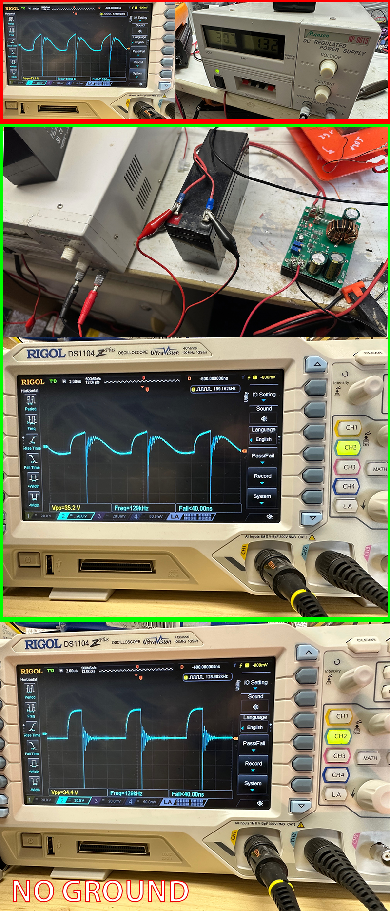
Secondly, I started with the different loads and voltages, the best ones till now is with the 24v50w car bulb, all the photos below are with that load. I looks I'm a bit closer to the goal, the red outline photos are with the PS directly to the mosfet with driver, the second ( green outline) is from the dc-dc inverter at the end, ( PS=ACCU=DC-DC INVERTER), the third one is with no ground to the power supply...It is clearly visible that I got the right waveform but still without the current drop, just the light dimmer all the way, except I got this oscillogram like in the photos at around 130 Khz, 25% duty.Any thoughts?

have a nice night or day, e😋

Close