One Plus One Minus One

  • 1.6K Views
  • Last Post 06 April 2023
cd_sharp posted this 28 October 2022

My friends,

Long time no talk, I had some rough time like everyone. This is an update of the OnePlusOneMinusOne setup, based on Non-Inductive Coil experiment video 7 :

I added an extra coil and I noticed if I short it, it increases the output voltage. There are lots of details that I modified from the POC setup Chris was using and I did them to solve specific issues.


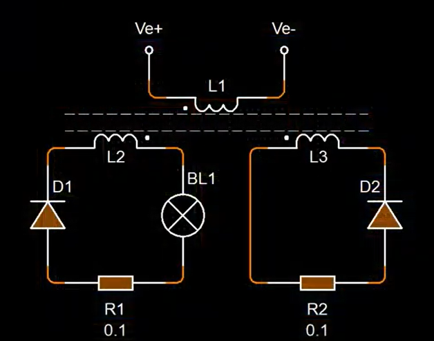
After I'll make the most out of it I'll drop a full schema and details disclosure.

A detail: the blue current is peaking around 0.3 amps and the yellow current trace is using the same measurement scale.

I'm still active in experiments, but I lack the time to post. Hopefully, that will change!

Stay strong!


If you know how to build such a device and you're not sharing, you're a schmuck! - Graham Gunderson

Atti posted this 05 April 2023

Hi baerndorfer.

in other words! it works for me on the e-cores very well.


Can you show me the parameters of this layout? So some more information. Thank you.

Oh, sorry.Is this about the E-cores in the shared information on the previous page?

Atti.

baerndorfer posted this 06 April 2023

hi atti,

nothing special here. i use a mosfet to switch a coil on the low side to get a sharp pulse. this creates a magnetic field in the first e-core. the second e-core duplicates the field from first one. the coil on secondary can be opposing style or ordinary. i managed to reach equal masses between primary and secondary and this results in more output.

i'm sure it works on other setup too.

depending on components you can reach switching frequencies between 100 and 200kHz. 1-2% ON-duty at 1.4kV. this is what i can handle without running into problems.

regards

B

Close