Square Wave Oscillator Off-Grid

  • 634 Views
  • Last Post 01 August 2023
Jagau posted this 13 August 2020

Hi all
I would like to share with you this little square wave oscillator which works the same as a function generator and which operated on battery which can vary from 6, 9 or 12 volts DC according to your needs.


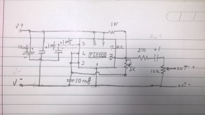
The heart of the oscillator is a TLC555 from the CMOS series which has very low power consumption and is completely different from the old NE555.

It has a 10K potentiometer to vary the frequency from 13Khz to 130Khz and another 5K potentiometer to increase the amplitude of the signal at will.


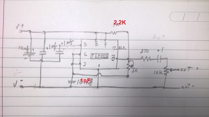
A drawing of the schematic that I present to you freehand

It can be easily changed by changing a single resistor and a single capacitor.

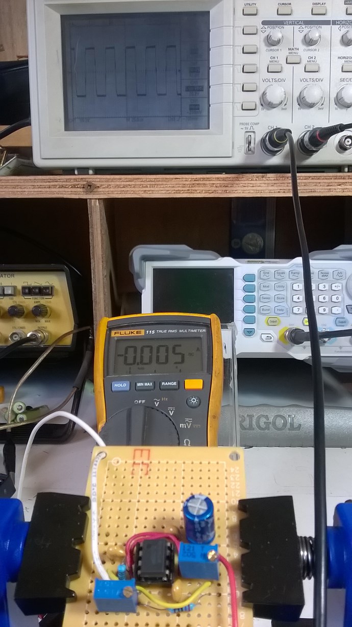
5 ma on 9 volts battery here


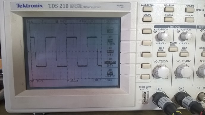
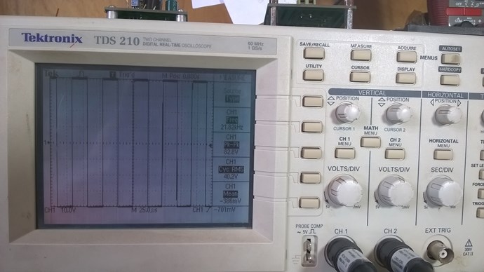
The particularity of this oscillator is that the output voltage changes from positive to negative through zero in the center. This is the AC square wave shape.

Most of these freely sold circuits are above zero volts they are only DC square wave and could not be use for experimentation.

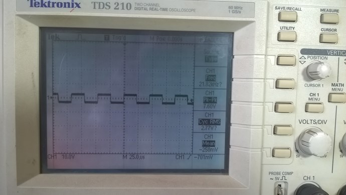
Very low or high amplitude at your choice


This way you are isolated from the electrical network and have greater freedom of measurements without ground return.

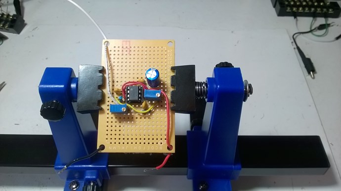
 I also hope for those who would like to join us and experiment with us and do not have a function generator, this is the ideal opportunity, easy to assemble and inexpensive.

Jagau

  • Liked by
  • AlteredUnity
  • Inception
Order By: Standard | Newest | Votes
Jagau posted this 13 August 2020

Hi all
I would like to share with you this little square wave oscillator which works the same as a function generator and which operated on battery which can vary from 6, 9 or 12 volts DC according to your needs.


The heart of the oscillator is a TLC555 from the CMOS series which has very low power consumption and is completely different from the old NE555.

It has a 10K potentiometer to vary the frequency from 13Khz to 130Khz and another 5K potentiometer to increase the amplitude of the signal at will.


A drawing of the schematic that I present to you freehand

It can be easily changed by changing a single resistor and a single capacitor.

5 ma on 9 volts battery here


The particularity of this oscillator is that the output voltage changes from positive to negative through zero in the center. This is the AC square wave shape.

Most of these freely sold circuits are above zero volts they are only DC square wave and could not be use for experimentation.

Very low or high amplitude at your choice


This way you are isolated from the electrical network and have greater freedom of measurements without ground return.

 I also hope for those who would like to join us and experiment with us and do not have a function generator, this is the ideal opportunity, easy to assemble and inexpensive.

Jagau
  • Liked by
  • AlteredUnity
  • Inception
UndisclosedMember posted this 13 August 2020

Hey Jagau,

This is awesome! A very nice, cheap project for anyone to take on that needs a small oscillator!

Thank You for Sharing! This is awesome!

Best wishes, stay safe and well My Friend

  • Liked by
  • Inception
UndisclosedMember posted this 16 August 2020

Great addition to the group. Has a very tight transition time but then cmos is very fast usually. Big thanks and will add to the bench soon as can order the tl555.

  • Liked by
  • Inception
Jagau posted this 18 August 2020

Hello UndisclosedMember


Yes the CMOS TLC555 has quite surprising performance especially when looking at the manufacturer's specs:

Minimum and maximum Rise time and fall time are very fast, they approach those of manufacturers of high quality function generators. These are very important parts when making oscillators.

I will be producing an addition to this oscillator shortly
to be continued

Jagau

  • Liked by
  • Inception
UndisclosedMember posted this 20 August 2020

Hello Jagau, the TLC555 is a very good choice. If you only need it to drive high impedance output like most gate drivers then it could be made significantly more efficient (likely less than 1ma at 10kHz).

  • Liked by
  • Inception
Fighter posted this 21 October 2020

Hi Jagau,

As I found in specs TLC555CP (the version I found) is capable of going to about 2 MHz.

I tried to find a online calculator for resistors and capacitor to build one capable to go to 250 KHz maximum.

So far didn't found a useful calculator, the schemes for which they are calculating are different than your schema.

What values would you recommend to change for a version with 250 KHz maximum frequency (or maybe more, higher frequency is better) ?

For your schema how are these values calculated based on the desired frequency range ?

I intend to build one for a QLED experiment.

Thanks for help.

"If you want to find the secrets of the universe, think in terms of energy, frequency and vibration."
Nikola Tesla
  • Liked by
  • Inception
Jagau posted this 21 October 2020

Hello Fighter
When I built this oscillator I used the following formula:
In theory the generator's frequency can be calculated as follows:


f = 0.72 / (R1 * C1)


However in the reality the obtained frequency tends to be lower, especially at the higher end of the generator's range. This can be compensated for by adding a variable resistance rather than a fixed resistance.


I also kept some assembly notes to have different frequency ranges with a capacitor-resistor combination.
1 nF with 2.2 kOhm = 250 khz
1 nF 6.2 kOhm = 100khz
10 nF 2.2 kOhm = 30 khz
10 nF 6.2 kOhm = 10khz
0.1 uF 2.2 kOhm = 3.1 khz
A tip, it is best to use a potentiometer to vary the frequency as desired.

So for your project change the 5k pot to a 2.2k pot. at pin 3 the other pot (10K) at output is for amplitude only

and pin 2 change 10nf to a 1 nf capacitor.

Hope this help

Jagau

  • Liked by
  • Inception
Fighter posted this 21 October 2020

Sure, I intend to keep the variable resistors as in the schema.

So for a range up to 250 KHz it should be something like this ?

"If you want to find the secrets of the universe, think in terms of energy, frequency and vibration."
Nikola Tesla
  • Liked by
  • Inception
Jagau posted this 21 October 2020

Hi fighter

No it is the 5k pot you have to change for 2.2k 

So for your project change the 5k pot to a 2.2k pot. at pin 3 the other pot (10K) at output is for amplitude only

and pin 2 change 10nf to a 1 nf capacitor.

Jagau

  • Liked by
  • Inception
Fighter posted this 21 October 2020

Oh, okay. So variable resistor 5K becomes 2.2K. And the 10nF capacitor becomes 1nF. Right ?

"If you want to find the secrets of the universe, think in terms of energy, frequency and vibration."
Nikola Tesla
  • Liked by
  • Inception
Jagau posted this 21 October 2020

Yes

Jagau

  • Liked by
  • Inception
Close