AlteredUnity's successful ZPM replication

  • 3.7K Views
  • Last Post 23 October 2023
  • Topic Is Solved
AlteredUnity posted this 16 January 2023

Hey everyone, im glad you started a new community, its a shame your device went from "should be first device to replicate after Non-inductive coil" to a toy, to deleted.

300Turn coil : measurements were made with both coils on center of core at 1khz; Coils were then put at far opposite ends of top and bottom of core.

20awg;  L = 425mH; DCR = 1.73 ohms

150Turn coil : 20awg; L = 110.7mH; DCR = 0.818 ohms

This is a fast trial run, have more to come with some ideas that may improve opperation. With this configureation I still pull 7 watts of power, so there isn't a whole lot of feedback. 

The center tap is connected to cable running to my cars body ground; The scope is connected across load, with its ground on the DRAIN of mosfet. This may be the wrong configuration and reason for not lowering input.

Any pointers are appreciated.

Attached Files

Atti posted this 25 March 2023

Just because the input current is reduced does not mean anything....
Well, I strongly disagree. That's the most important behavior of a truly overunity device.


Sure, it's obvious. You know what I mean.

Atti.

Munny posted this 25 March 2023

I still think to really stump the nay sayers, it would be good to attach a watt meter inline with the power supply input.  Place the unit right in front of the power supply, so all the readings are clearly visible.  The watt meter will account for the little bit of power consumed by the power supply itself which should be almost nothing to run the display and the little onboard microcontroller.  If you want, you can get a baseline on the power supply by disconnecting the ZPM, show that in a separate image.  Those cross-checks of everything will leave zero doubt about what is happening.

Fighter posted this 25 March 2023

To be honest I don't care about naysayers. They gonna "sing" the same "song" even if you put a self-running device on their table.

Right now ZPM's circuitry (wires, connectors etc.) are in some boxes, I would need to find them and rebuild the circuitry. And I don't have time for that, hopefully soon I'll have some more time to continue with the experiments.

About the wattmeter, I tried that long time ago and it was inconclusive, it shown much more than the 60V/5A DC source can physically provide and the readings were jumping up and down. It was clear the power meter readings were messed up by ZPM. These things (power meters, standard hand-held non-contact measurement tools, standard multimeters) are made for 50/60 Hz to max. a few tens of KHz, not for hundreds of KHz where the ZPM is functioning.

Remember Editor's freezer being affected by ZPM ? If not check it here. I understood later why the power meter was affected even when placed on DC source's power cord.

Still, I used an more advanced power meter which (I'm quoting from its specs): "Acts like a wire so doesn't affect model's performance. Precision Alu-Chrom current sensing resistor, with only 0.001Ohms resistance and circuitry that draws only 7mA Uses DSP to increase ADC resolution and differential measurement amplifiers to increase noise immunity. Powerful, 8MIPS micro-controller.". I "forced" ZPM out of the optimal/resonance frequency so the consumption would be higher because the wattmeter is not built to measure currents lower than 0.100 A. and it confirmed the DC source's readings:

The small current difference (~ 0.01A) is because the power meter itself have a small consumption.

The probability of ZPM messing the readings of two different devices (at the same ZPM frequency but with different components, different reading sensors, etc. ) but still the devices to show the same readings is the same as the probability to play at the lottery for the first time in life and win the big prize then playing for the second time and win the big prize again.

Technically and statistically the probability is 0.

You can see more details here and here.

On my side the constant decreasing of DC source's readings when getting close to ZPM's resonance/optimal point (and that point is different with different loads) is the proof of ZPM's overunity. And if the DC source's readings would be messed up the values would jump up and down with big differences, the increasing/decreasing of the readings would not be so smooth.

But I don't want to derail AlteredUnity's replication thread with a different subject. 

Regards,

Fighter

"If you want to find the secrets of the universe, think in terms of energy, frequency and vibration."
Nikola Tesla
cd_sharp posted this 25 March 2023

Guys,

I recommend everyone to have a look at this video and the other videos related to the subject on the same channel:

Yoelmicro pointed out from the beginning this relationship in the ZPM. We just had no idea what impedance matching is.

Stay strong!

If you know how to build such a device and you're not sharing, you're a schmuck! - Graham Gunderson

Jagau posted this 05 April 2023

Hi Alteredunity

I don't know how your project is going, we can't hear you.
Which circuit you used for your ZPM replication??

When you have understood how it works at the exit you will have a beyoudunity system like this one.


As here you have 4.04 watts average power at the output, see how bright the output lamp is.

With an instantaneous power input  of 4.33 watts converted into an average power of 2.5 watts input power.

Jagau


AlteredUnity posted this 06 April 2023

Replying To: Jagau

Thanks for checking up, I just moved my bench upstairs and organized my stuff, I'm hoping by this weekend I will have something to show. For the past few weeks I've just been working on running a normal dc switched load and normal transformer to get a feel of correct scaling etc on oscilloscope to be sure I'm getting accurate measurements in future setups. Also getting better grasp on running a good efficient setup and impedance matching. Reading other post when i rewind my 150 turn coil I may adjust bobbin to meet 150 turns and still have 1/2 the wire weight of the 300 turn coil. It may come to having a slightly different turns ratio, so for now ill experimentwith what i have, get a grasp on what im seeing and why before adjusting other parameters.

AlteredUnity posted this 05 May 2023

Short update, it turns out my Rigol DS1054z math does include phase angle in measurements between voltage and current waveforms when using math function.

P = Vrms * Irms * cos(phase angle)


I wanted to verify this, so I made the following setup.
My signal generator ch1 connected to ch1 of scope, and ch2 of gen to ch2 of scope. Each channel set to same amplitude and frequency, but a phase difference of 45°.
For a sinewave we get:
Math(rms) = 1.05W of apparent power. 
Math(avg) = .745W of real power.
This is showing me the correct value for power would be Math(avg), which seems to take into account the cos(theta)  or phase difference between Voltage and Current(though phase will be around 44.8deg or 46.8deg not sure how its doing its math).
So for future power measurements using this oscilloscope I will be using Math(avg) for my calculations with confidence of correct measurements being returned. Here is a scope shot of an example. 

AlteredUnity posted this 03 June 2023

Finally got everything set back up. I went back to the setup with a filter coming out of my power supply, this is because without it its rly hard to read the actual values striaght off the source of the mosfet. I believe I have the correct measurement setups, and am still running circuit off the black power supply in the pictures.

Circuit(note N-mosfet is drawn incorrectly) :

SG settings:

Input Setup:


Input Measurements: CH1-Yellow(Voltage from PS), CH2-Teal(Current over .1ohm resistor to PS - ), CH4-Blue(Input Pulse from gate), Math(Purple: AVG:CH1XCH2):

Output Setup:

Output Measurements: CH1-Yellow(Voltage over bulb), CH2-Teal(Current through .1ohm resistor after bulb), Math(Purple: AVG:CH1XCH2):


I will replace photos later showing the gate of mosfet with my differential probe. Please let me know what you think, or what can be altered. I will get rid of the filter, and try other power supplies and loads. Still need to work on lowering my input.

There is so much to process from these scope shots. Also signals before and after the low pass filter. Will come back with explanations if I get time explore deeper.

Attached Files

Fighter posted this 04 June 2023

Hi AlteredUnity,

The input decreasing effect was demonstrated in other ZPM replications so obviously something is wrong.

Let's try to find the cause.

First I would simplify the circuit and make it look as closer as I presented it in my demonstrations.

These are the things I would do for the beginning:

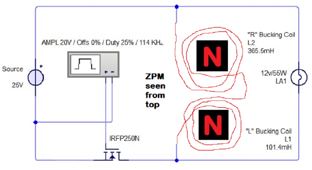
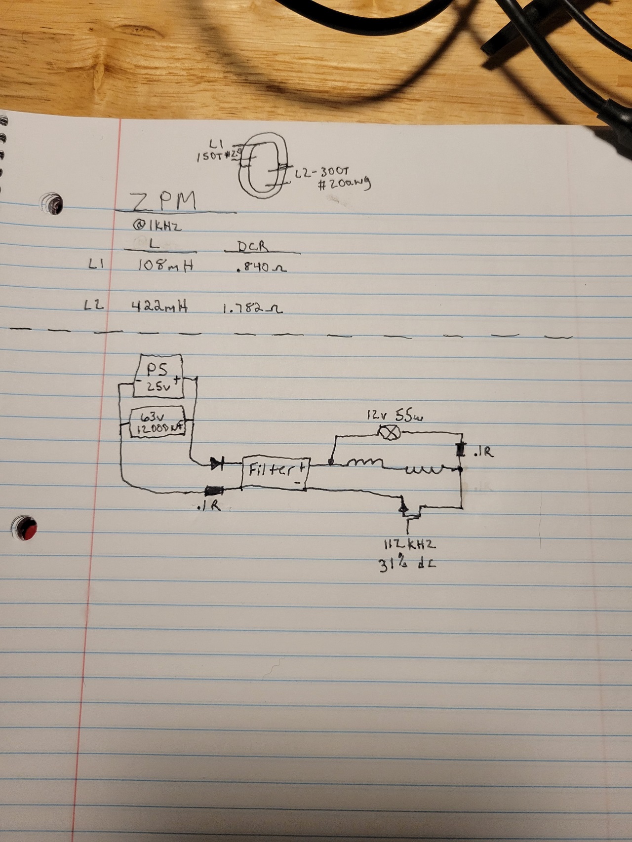
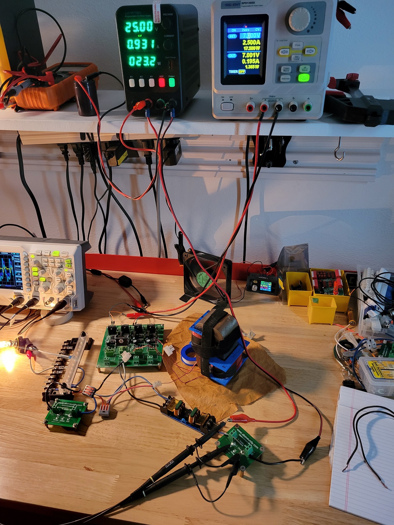
  • remove that filtering circuit, honestly I can't evaluate how those extra-coils and everything there is affecting the functionality of your device;
  • remove that diode, also I can't evaluate how it's affecting the device;
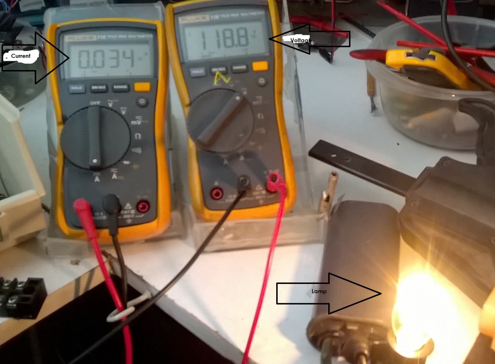
  • remove those measurement resistors on input and output, any resistor added to the circuit is seen by ZPM as a load and it's changing its resonance frequency, even connecting the oscilloscope's probes is changing the optimal resonance frequency of my ZPM, when I do that I need to find a new frequency.

The idea is first to make your device reproduce the input decreasing effect without any other things in the circuit. Then once you see the effect you can add other things and see how these things are affecting the device's behavior. It makes no sense to add anything in the circuit now, as long as the input decreasing effect is not present you'll not measure an actual ZPM replica.

I don't know if your DC source is using grounding or not, maybe you should set it to use grounding so we make sure the circuit is as I've shown in my demonstrations. I am aware about the risks when the oscilloscope is using grounding too but for now we don't need the oscilloscope, the goal is to reproduce the input decreasing effect.

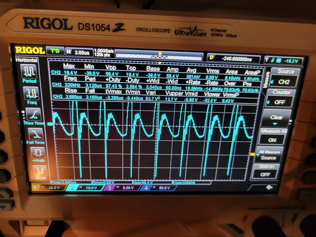
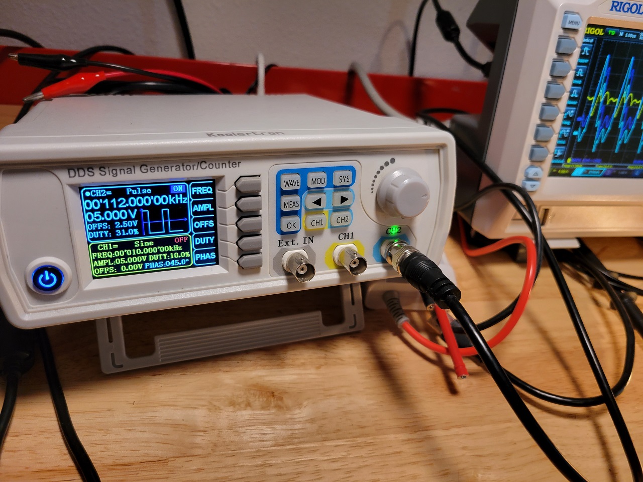
With these things being done I would proceed with a frequency sweep like I've shown here:


Note: the frequency sweep above is made when I have halogen light bulb on ZPM's output, that's more precise as the halogen light bulbs are lighting up instantly, they don't have a delay like the resistive light bulbs.

For making frequency sweep with resistive light bulb this is how I'm doing it:


Why I'm asking you to do a frequency sweep ? Because maybe the frequency you're using is not your device's resonance frequency. With my ZPM if I go below 80 KHz the light bulbs are still shining but the input current is rising close to 1A and even more, which looks like what I see on your source's readings.

If frequency sweep doesn't work as in the videos above then something is wrong in how your ZPM replica is built.

It's hard to see how your coils are built, especially their winding directions because that's important too. And it's hard to follow the winding directions of your coils and how they are connected to each other because your coils are not placed on the core like on my ZPM (I don't know if their positions on the core are important for the device's functionality or not).

Basically when looking at your device from above your coils should have clock-wise winding directions and to should be connected like I've shown in one of my posts here:

I took a photo of my ZPM and noted the clock-wise winding directions of the coils:

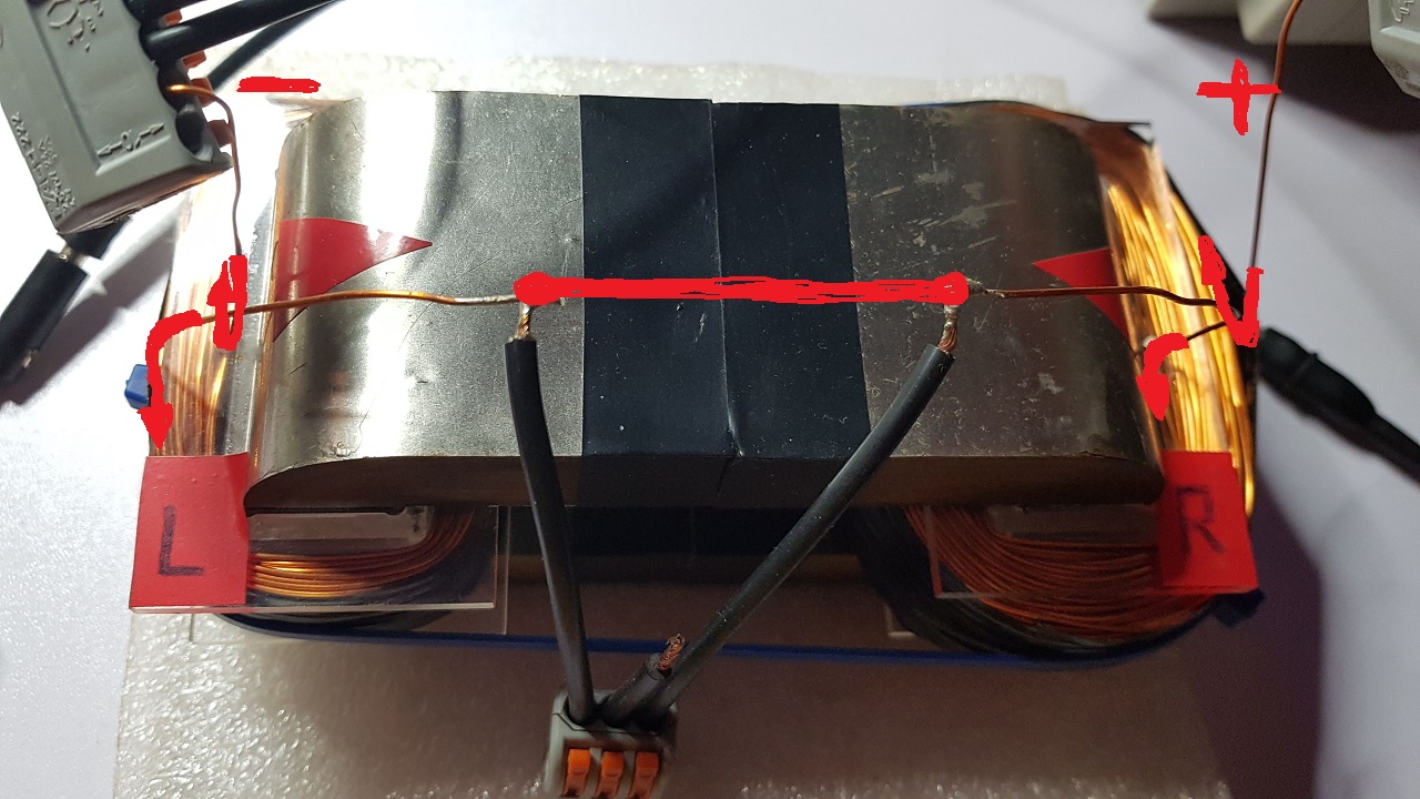
As you can see the begining of each coil is starting in clock-wise winding direction but the begining of the bigger coil is connected to the ending of the smaller coil. I also noted the electric polarity of the coils: the end of the bigger coil is always connected to + and the beginning of the smaller coil is always connected to -.

I hope my post helps and could be a beginning in finding the cause why the input decreasing is not present.

Regards,

Fighter

"If you want to find the secrets of the universe, think in terms of energy, frequency and vibration."
Nikola Tesla
AlteredUnity posted this 04 June 2023

10-4, no i havent actually tried a sweep, i was just mocking my previous setup for measurement, but will sweep and implement changes tonight; More wire just arrived today, I'm still using old coil wound in opposite direction from the bigger one. May take a little to wind the new 150turn coil, but like you said, I will get rid of everything that's just adding unnecessary complexities when I haven't fully got the effects yet or at least to a degree that is unquestionable. Thank you.

Close