AlteredUnity's successful ZPM replication

  • 3.7K Views
  • Last Post 23 October 2023
  • Topic Is Solved
AlteredUnity posted this 16 January 2023

Hey everyone, im glad you started a new community, its a shame your device went from "should be first device to replicate after Non-inductive coil" to a toy, to deleted.

300Turn coil : measurements were made with both coils on center of core at 1khz; Coils were then put at far opposite ends of top and bottom of core.

20awg;  L = 425mH; DCR = 1.73 ohms

150Turn coil : 20awg; L = 110.7mH; DCR = 0.818 ohms

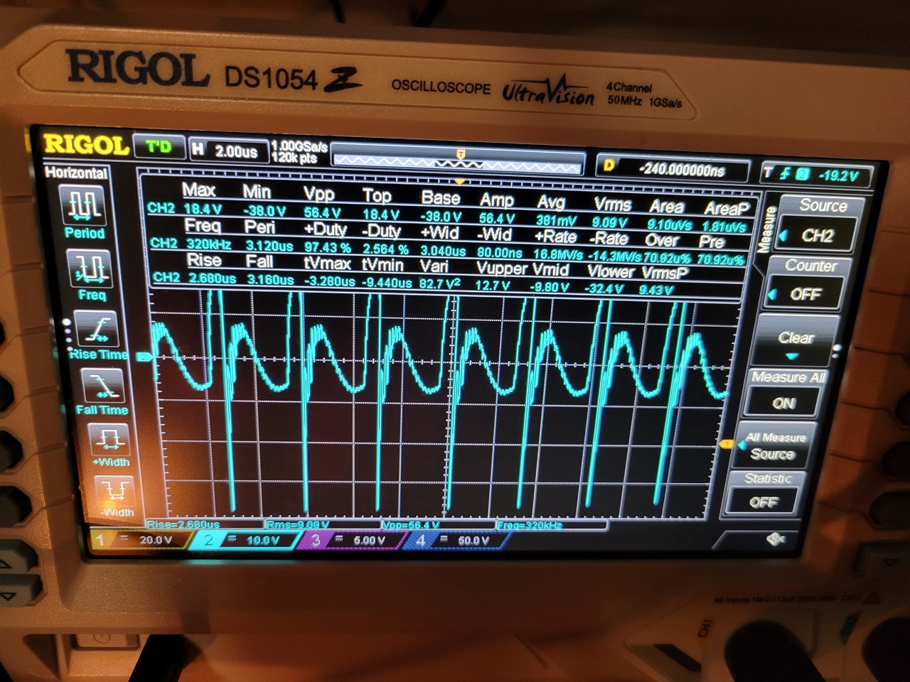
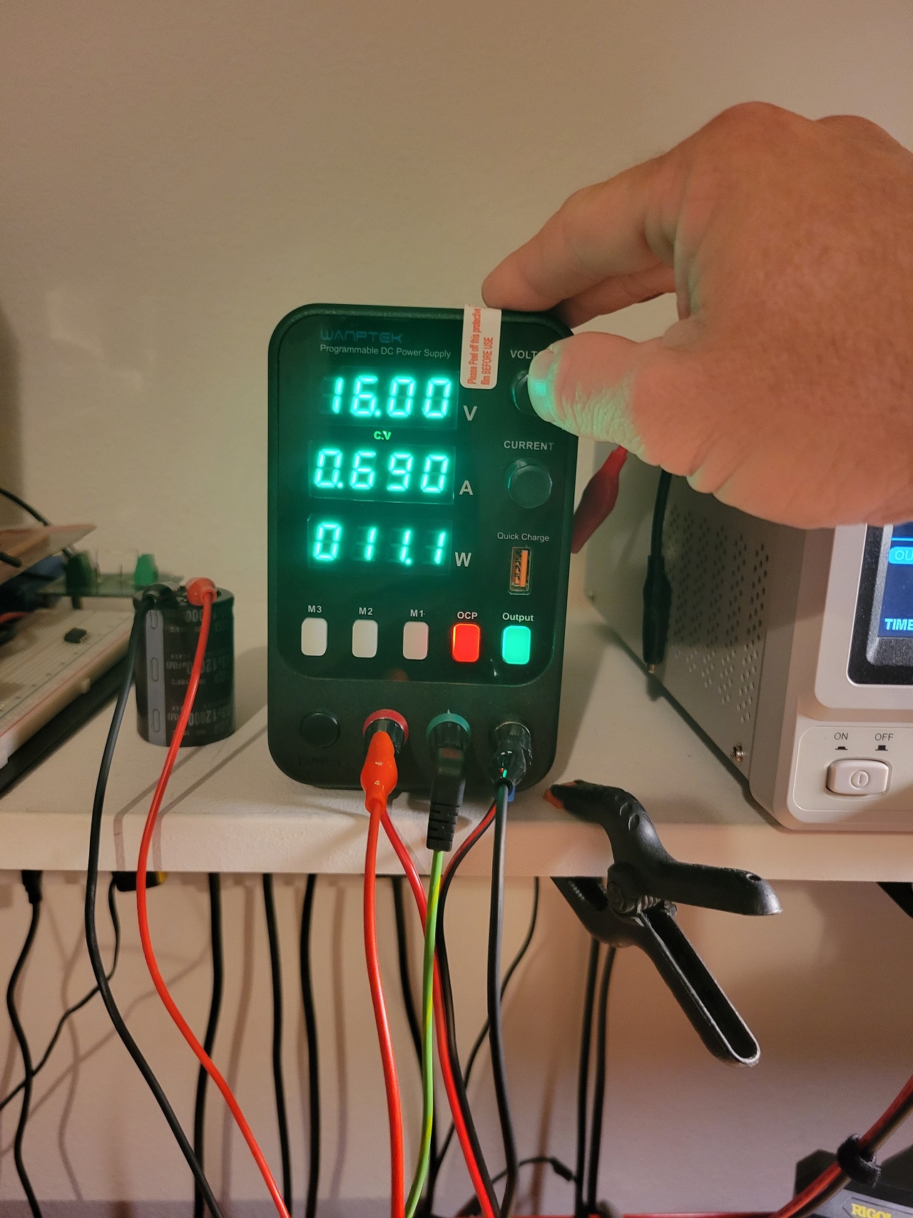
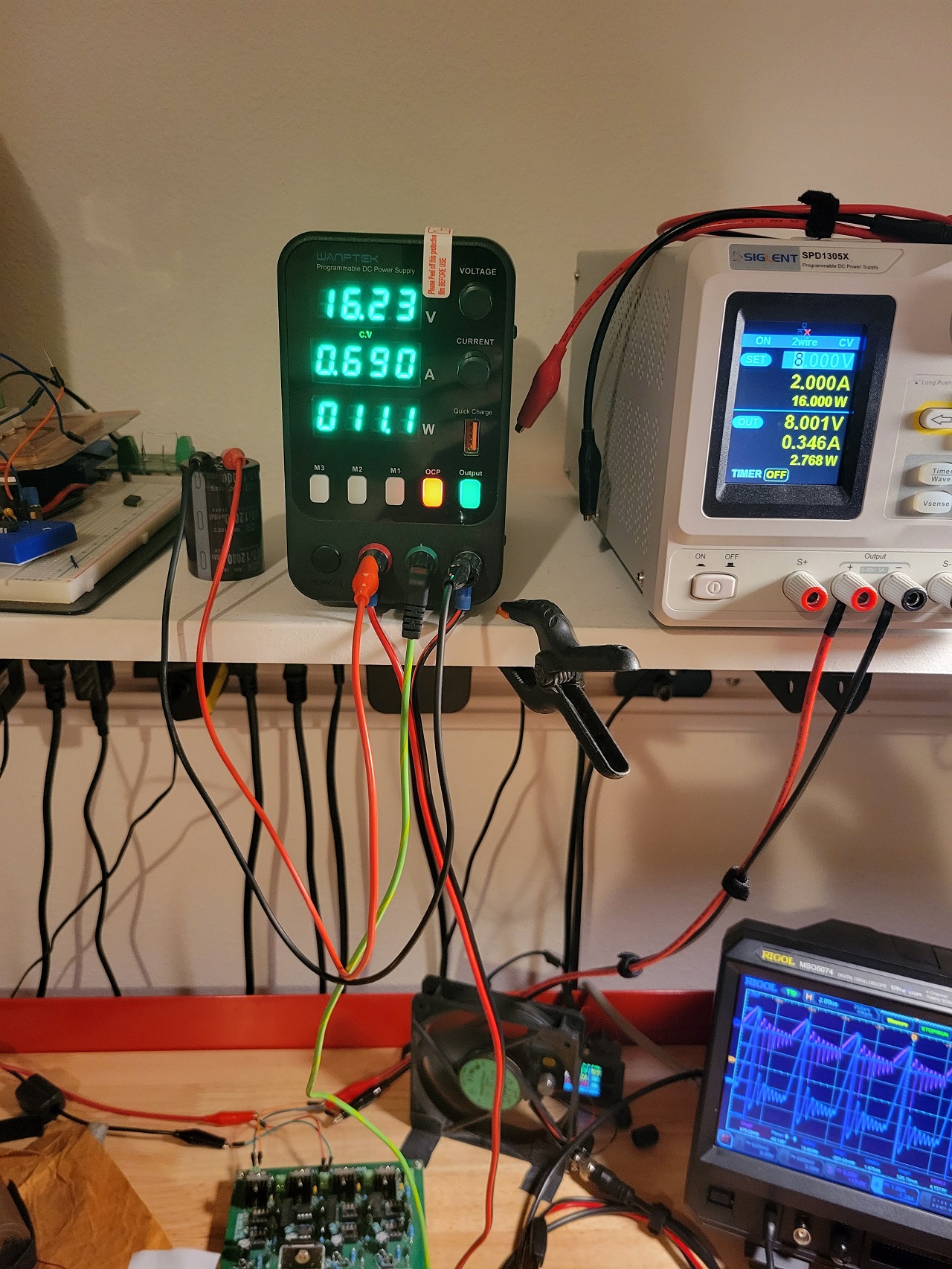
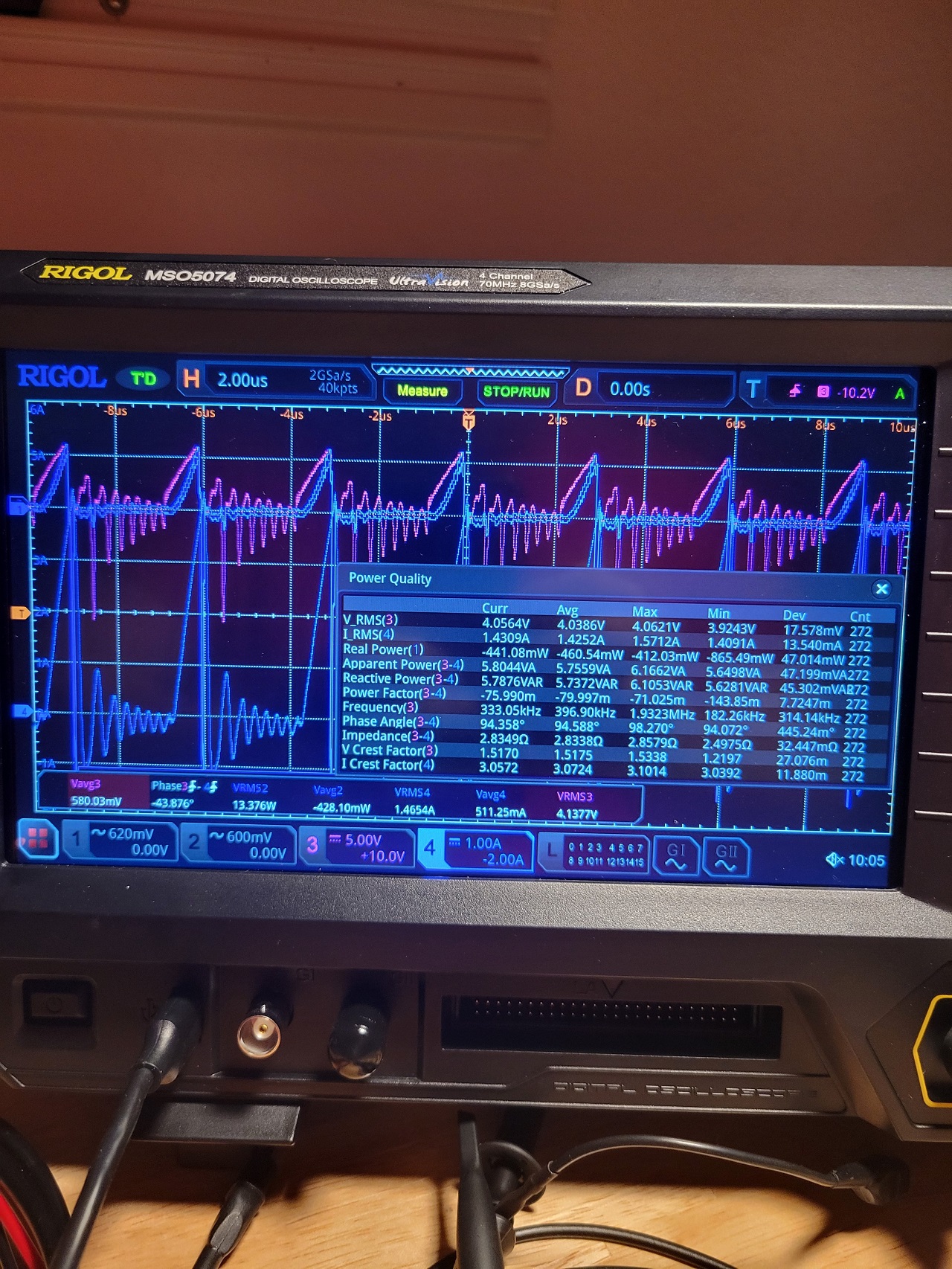
This is a fast trial run, have more to come with some ideas that may improve opperation. With this configureation I still pull 7 watts of power, so there isn't a whole lot of feedback. 

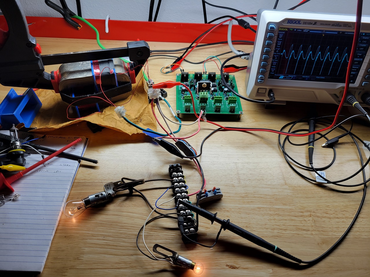
The center tap is connected to cable running to my cars body ground; The scope is connected across load, with its ground on the DRAIN of mosfet. This may be the wrong configuration and reason for not lowering input.

Any pointers are appreciated.

Attached Files

AlteredUnity posted this 23 October 2023

Still haven't had a lot of time, just got ZPM laid back out. Ill make note of what I observed in the ten min of getting to tune it. Just making notes because it may play a big roll in the effects of the configuration. 

The output on the load isn't great, but thats not what im showing this for. While tuning I realized my powersupply voltage started to increase. It is set at 16v, and while hitting certain frequencies, it goes to 16.23V while the input current drops about 20ma. Maybe helpful. Freq = 333kz, duty cycle 23%. 

Also I got a new scope, having fun and learning it better. The picture shows a Power Analysis function available on the scope, keep in mind this function to used to measure AC input line, though here on the output it shows im using -463mW of Real Power to my load, im still learning why this is or what it means. 

This is clicking button on power supply to show its current set voltage while its running:


This is the voltage its displaying its putting out(ive seen this on some boost converters in the past when a cap wasn't discharged and output was shut off, it shown the capacitors charge until it depleted) :

And here is the scope shot with voltage across the load(measured with differential probe), and current through the load(measured with current probe):


Jagau posted this 23 October 2023

Well done Alter

This new toy will give us a lot of pleasure.

Yes the power analysis software package is very interesting, when I look at your last image everything corresponds very well with Cos Phi, the values are exact when we do the calculations manually to double-check.

The software calculates in real time the correct average values on which we can rely. As you may have noticed when Cos phi exceeds 90 degrees, nothing is consumed at the source and there is even, as in your case, a small negative 460.5 milliwatt who is returned to the source. Lots of pleasures in perspective.

I need to buy a new differential probe, which one do you use?

Are you happy with his performance?

Is this an active or standard differeintial probe?

You will respond when you have time.

Thank you for sharing

Jagau

AlteredUnity posted this 23 October 2023

Thank you Jagau for the explanation, I learn more every day. My differential probe is "Micsig DP10013 Differential High Voltage Probe". It's well worth it, same with the "Micsig Oscilloscope Probe CP2100A AC/DC Current Probe 800KHz", is very accurate(the .1ohm resistors I use aren't as accurate because of the changing values at different frequencies can be misleading, but may just need better resistors.

While measuring I use the precision measurement option to use the whole memory buffer, not just the screen.

Jagau posted this 23 October 2023

Thank you for the feedback

I should receive mine soon, will let you know for testing result.

Have a nice day.

Jagau

Close