BTG research

  • 5.1K Views
  • Last Post 07 January 2023
Vidura posted this 03 August 2022

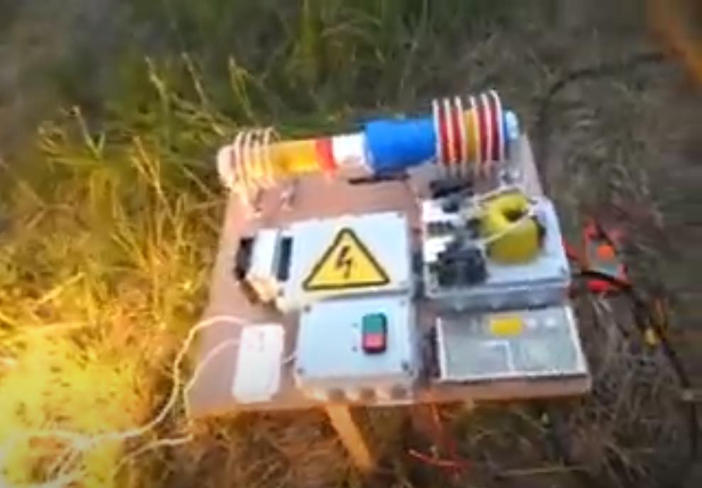
Hello Friends, I will import this thread; from the backup forum to the public category ,it is dedicated to the BTG devices like the ones shown by Ruslan and Akula. The Goal is to gain knowledge about the involved principals, and hopefully to achieve a working, self-feeding machine. Regarding the tier2 category , I want you to know that I was really tented to post for general public, and certainly the thread will be moved in the replications category when the time is right. But I also know that various persons got in serious troubles , and likely a young man lost his live, because this is the kind of devices produced in series would sensibly cut in the profits of the big energy companies.

We will in a first step go in diakoptik manner thru the different parts of the device and make different kinds of experiments and tests to get basic understanding of how this devices are working, and the interaction of the different parts. Also we will collect information from various sources from the original Builders. I would encourage those of you , who are interested in following or participating in this project, to read the thread about longitudinal waves , as this describes one of the  basic physical principals involved in this device.

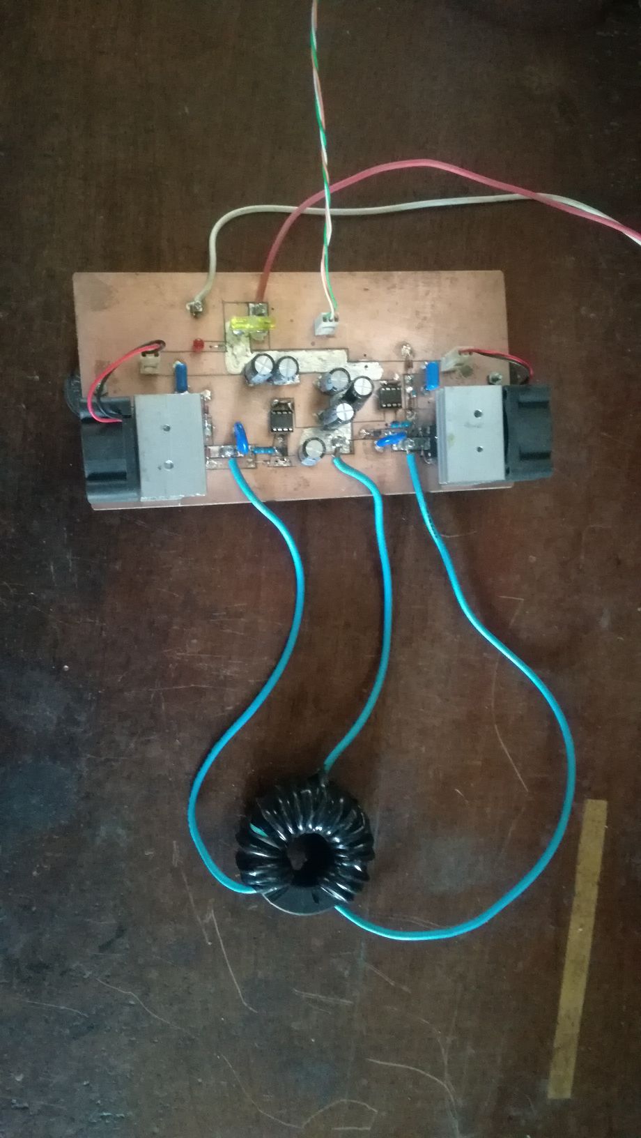
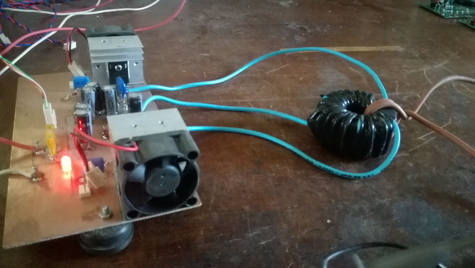
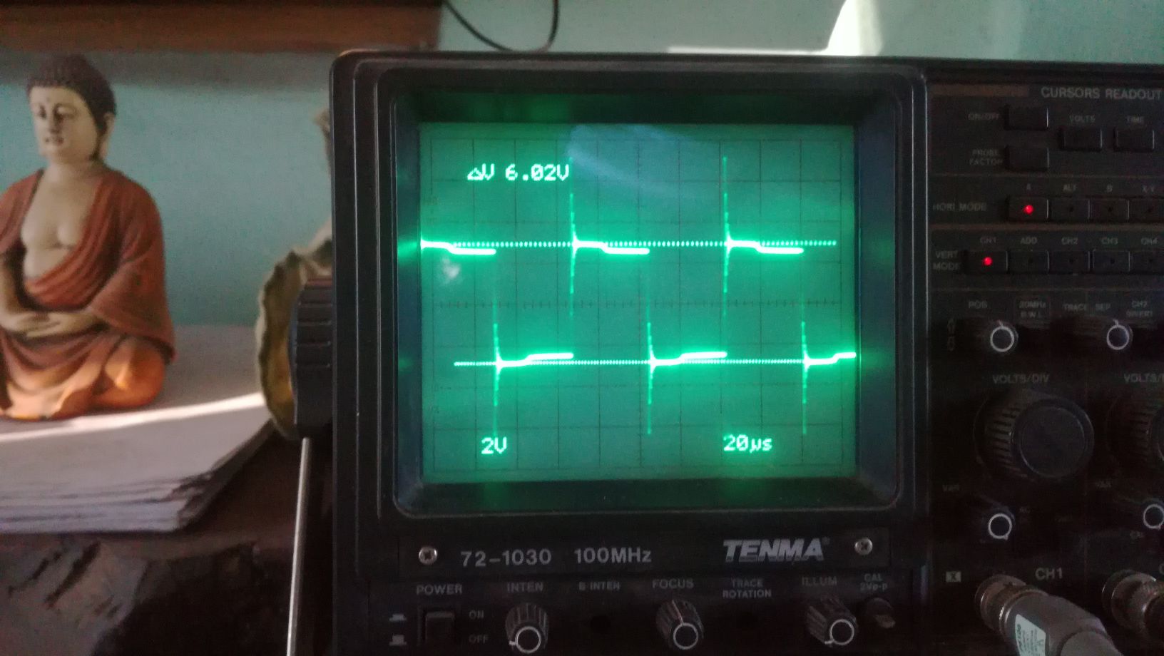
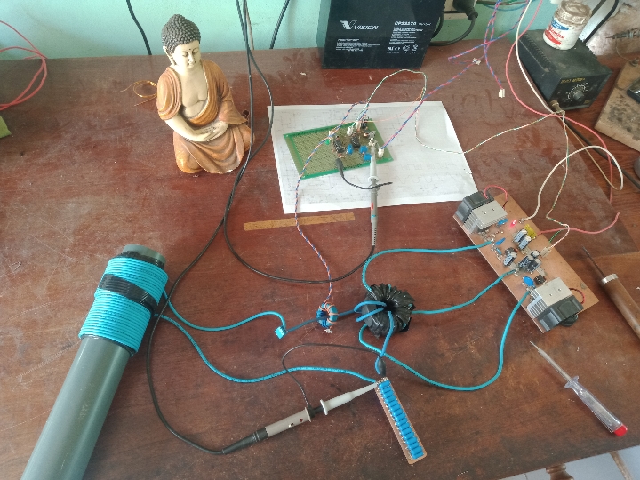
The First Part of the device we will cover is the push-pull converter. It's function is pumping charges, an analogy would be the electron-gun in the CRT, it is the source of charges. There is no magic in this part, it is just common EM technology, there are different topologies which could be used, half or full bridge would be suitable. For low frequency devices like the Kapagen also an of the shelf silicone steel transformer could be used. It is important that the output is AC. In the research we will stick to the push-pull topology for the ease of switching the two low side IGBT's. Here some images from testing this stage:

As I have time ,Ill continue to upload content and updates or corrections.

Vidura

Vidura posted this 30 November 2022

Hi all, as I was working on a new hardware, here some updates. First I wanted to clarify a few things regarding the general design concepts. There are various of this BTG type devices, which are all based on the same physical principles, but there are different engineer solutions and design options. Therefore also some differences in the way how they are excited, how the resonator(s) are designed, and how the power for the load is extracted. When Ruslan was posting on the Russian forum he gave a lot of hints and explanations(no schematics!), but few understood. One component of all these machines is the source of scalar waves or impulses. This can be a Tesla resonator, a Kacher-Brovin or a nano-pulser circuit. The other component which is present in all we could call the main resonator, which again can have various different hardware designs. As physical concept it can be designed as quarter wave resonator, halfwave  and less common  3/4 or full wave for standing waves. This designs requires a separate winding for the removal of power, as direct loading is not convenient. The other option is a traveling wave resonator, this requires at least one full wavelength for resonance, or multiples of it. The advantage is that in this case a direct removal of power (keeping the load fairly constant) is possible. But it can also be done indirectly. Relaying on wave theory , there would be different driving methods convenient, as parametric for the standing wave resonators, and with the same resonant frequency and period, but phase shifted for traveling waves. With the new hardware I will be able to test this by experiment, proof or disproof this concepts.


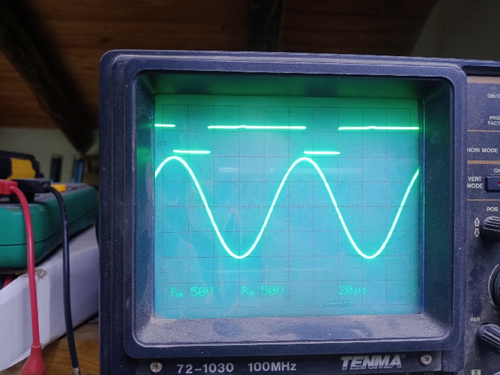
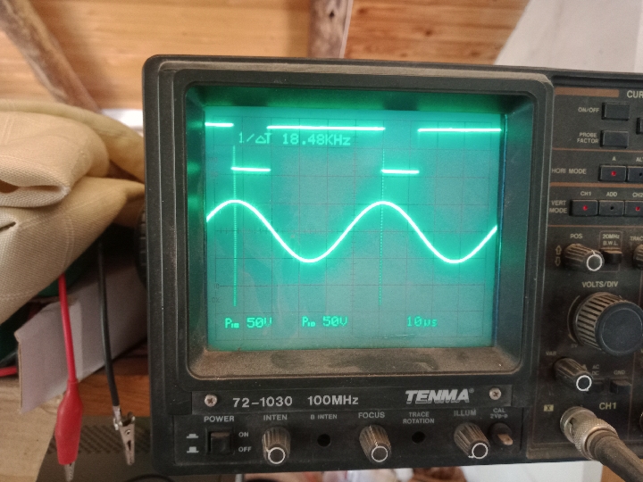
This would be the inverted signal for the modulation of the Kacher-Brovin for parametric excitation.

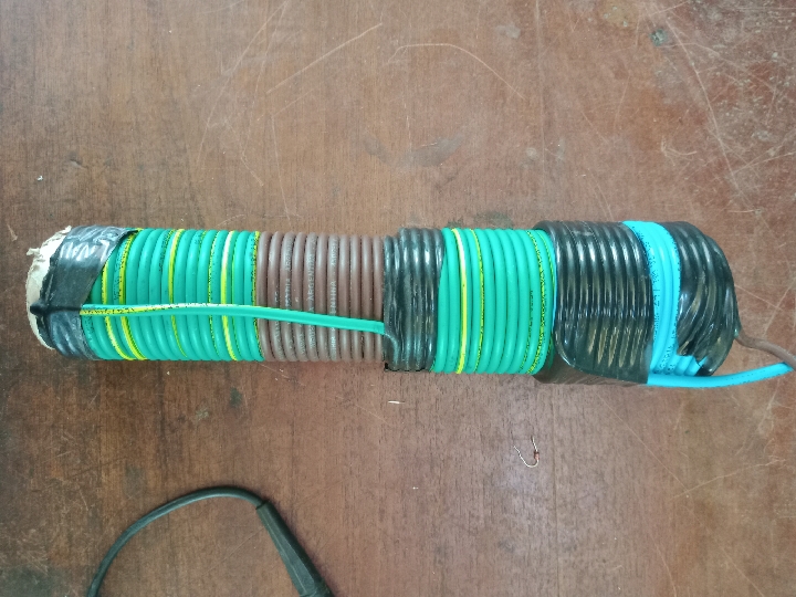
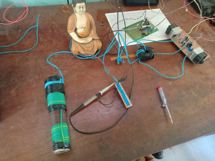
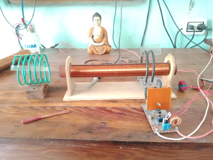
Below a "reduced grenade coil" for inductance and resonance test:

It's reduced due to the high copper prices, and I run out of stock.☺️

Vidura

Itsu posted this 02 December 2022


Thanks for showing Vidura,

So you use the Push Pull (yoke / toroid) around 18KhZ to drive the Grenade coil and series capacitors into series resonance.

Normally this series LC consists of the Inductor coil (around the lower part of the Grenade) and the series capacitors, but this is to show the relation between resonance signal and (inverted) modulation signal if i understand correctly.


Itsu

Vidura posted this 02 December 2022


@Itsu


The images shows the relationship between the main resonator and the modulation signal, in this case for parametric excitation. Anyway for the layout with a grenade coil the signal should be extended to half of the period for better performance, as it is a circuit with lumped parameters, a travelling wave resonator.


If we consider the physical processes taking place in the BTG,  being the same as in the kapagen and the eternal flashlight, then it becomes clear that various layouts and combination of components are possible. I am very confident, that the only reason for such few replications are due to the lack of understanding this underlying principles. There are millions of skilled and smart people all over the planet, but without knowing what we have to look for, the chances to get this working are like a lucky strike in the lottery.

So we have a source of high energy scalar waves or pulses as one component, then we have the main resonator, which has a resonant frequency by orders lower (mostly!). In this main resonator the process of "energy pumping" takes place, or better a transformation from one form of energy into another form more convenient for us. It is something like a heat pump, but of course with other manifestations of energy.

Then there is another part, which has the function of dissipating a form of energy at a different level. If you familiarize yourself with the thermoacoustic machines, you can see the similitude, there has to be a gradient of temperature, hot on one part, and cold on another, and the oscillations will start by itself. In most BTG devices this is the grounding wire, which is usually quite long. At small energy levels it could be the chassis or enclosure of some components as well. Then there is usually another part, which is used for removal of the output power. It is not mandatory, but the process of removal has to be controlled some way, otherwise it could stop the main resonator. If we have a constant load, it could be linked directly to the main resonator, which will be in LCR resonance in this case, but it might be more unstable.

The main resonator can also be driven by a separate coil in LC series resonance and the push pull for example, as you have stated  above, but the process remains the same.

Vidura

Itsu posted this 02 December 2022

Hi Vidura,

Great info, so it’s the "main resonator" (Grenade) which needs to be in resonance too to produce the "energy pumping" process.

Many diagrams out there show not really that this Grenade is put into resonance, but instead the Inductor is put into series LC resonance to drive the Grenade.

I have tried to get both the Inductor and Grenade (closely coupled) into resonance, but this fails as they get over coupled and reject their resonance peaks.

So, the Grenade is most important to get into LCR resonance and then have the correct circuitry for removal of the output power from the Grenade.

Thanks so far,  

Itsu

Vidura posted this 09 December 2022

Hi all, the last time I was working on the improvement of the Kacher-Brovin driver. It took many hours on the bench, something tricky the circuit. Four drivers and three MOSFET get fried on the way, but finally it came out well. Below short video:


Next I will add the push-pull and main resonator, I thought to test some different options of coils and layout, as far as resources allow.

Vidura

Itsu posted this 09 December 2022


Vidura,

looking very nice, the driver looks very efficient now with only about 9.6W input.

Also the modulation of about 10kHz comes in the direcrion of what is needed (15-25kHz).

Would be great to see the modulation pulse train on the scope together with the Kacher output one time.

Looking forward to your next steps.

Itsu

Vidura posted this 10 December 2022

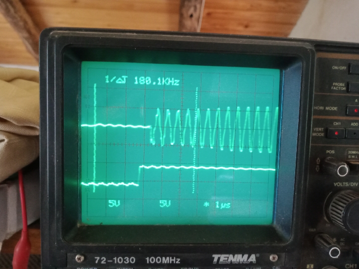
Here is a new coil for the Kacher-Brovin resonator; the reduced diameter allowed to increase the resonant frequency and thus the response time to the modulation signal is much faster.

As the number of turns is +500 the emitted scalar waves are strong enough.


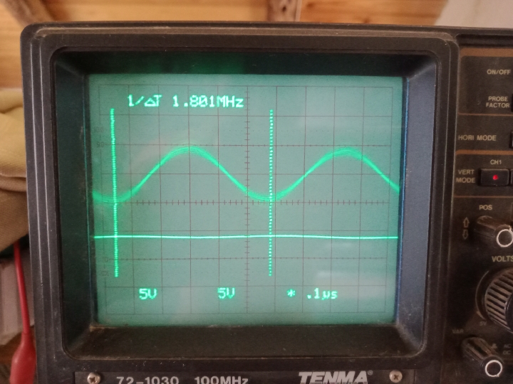
With the antenna attached, the resonant frequency is 1.8 MHz.

Below you can see the comparison with the modulation signal, which is still provided by the FG.

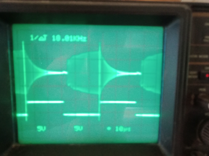
Here with a modulation of 18khz@50%

It can be noted that the start-up of the circuit is very fast, of course the decaying of the dampened wave  after the shutdown is present.

There is some ringing because the scope is not grounded.

Due to the high ambient temperatures, we have 40ªC these days, I found that the driver becomes very hot, so for a reliable operation this needs to be improved further.

Vidura

Itsu posted this 10 December 2022

Vidura,

so the antenna has a big influence on the resonance frequency pulling it down to 1.8MHz.

Great modulation at 18kHz, this should be useable.

Perhaps increase (or decrease) the FG somewhat to get a still narrower HF kacher pulse, then the impact of the antenna on the Inductor or Grenade coil would be maximized.

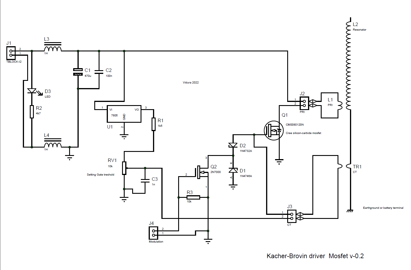
Does the diagram presented here: https://www.beyondunity.org/thread/btg-research/?p=4&order=all#comment-e7a04879-3edc-4968-92d0-af590041531d is still is the present on?

Itsu

Vidura posted this 10 December 2022

Replying To: Itsu

itsu, the link didn't show any schematic diagram If you ask for the Kacher driver, it is different from the other.

Vidura

Itsu posted this 10 December 2022

Vidura,


the link suppose to go to this diagram:

So in time could you present an update to this diagram then.


Thanks,  Itsu

Close