BTG research

  • 5.1K Views
  • Last Post 07 January 2023
Vidura posted this 03 August 2022

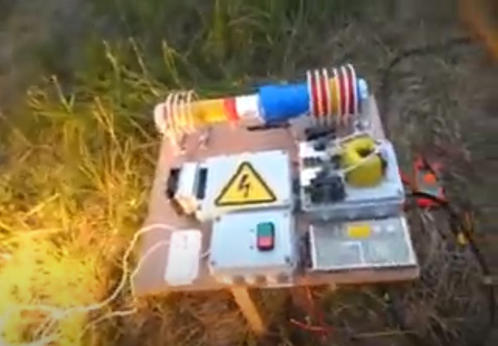
Hello Friends, I will import this thread; from the backup forum to the public category ,it is dedicated to the BTG devices like the ones shown by Ruslan and Akula. The Goal is to gain knowledge about the involved principals, and hopefully to achieve a working, self-feeding machine. Regarding the tier2 category , I want you to know that I was really tented to post for general public, and certainly the thread will be moved in the replications category when the time is right. But I also know that various persons got in serious troubles , and likely a young man lost his live, because this is the kind of devices produced in series would sensibly cut in the profits of the big energy companies.

We will in a first step go in diakoptik manner thru the different parts of the device and make different kinds of experiments and tests to get basic understanding of how this devices are working, and the interaction of the different parts. Also we will collect information from various sources from the original Builders. I would encourage those of you , who are interested in following or participating in this project, to read the thread about longitudinal waves , as this describes one of the  basic physical principals involved in this device.

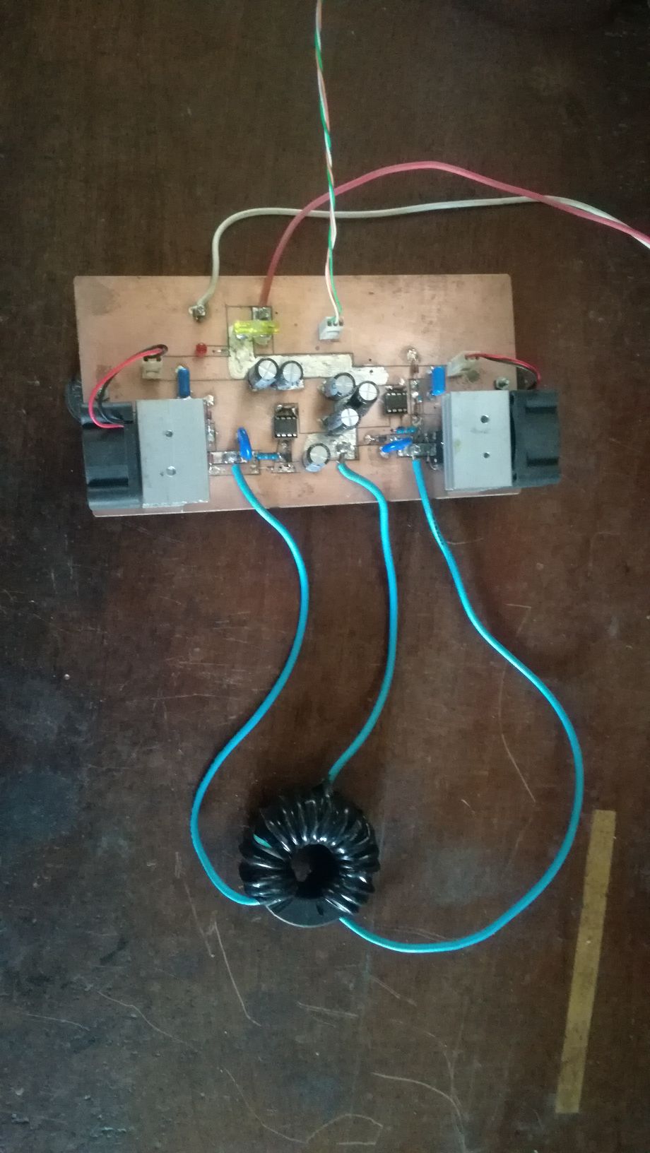
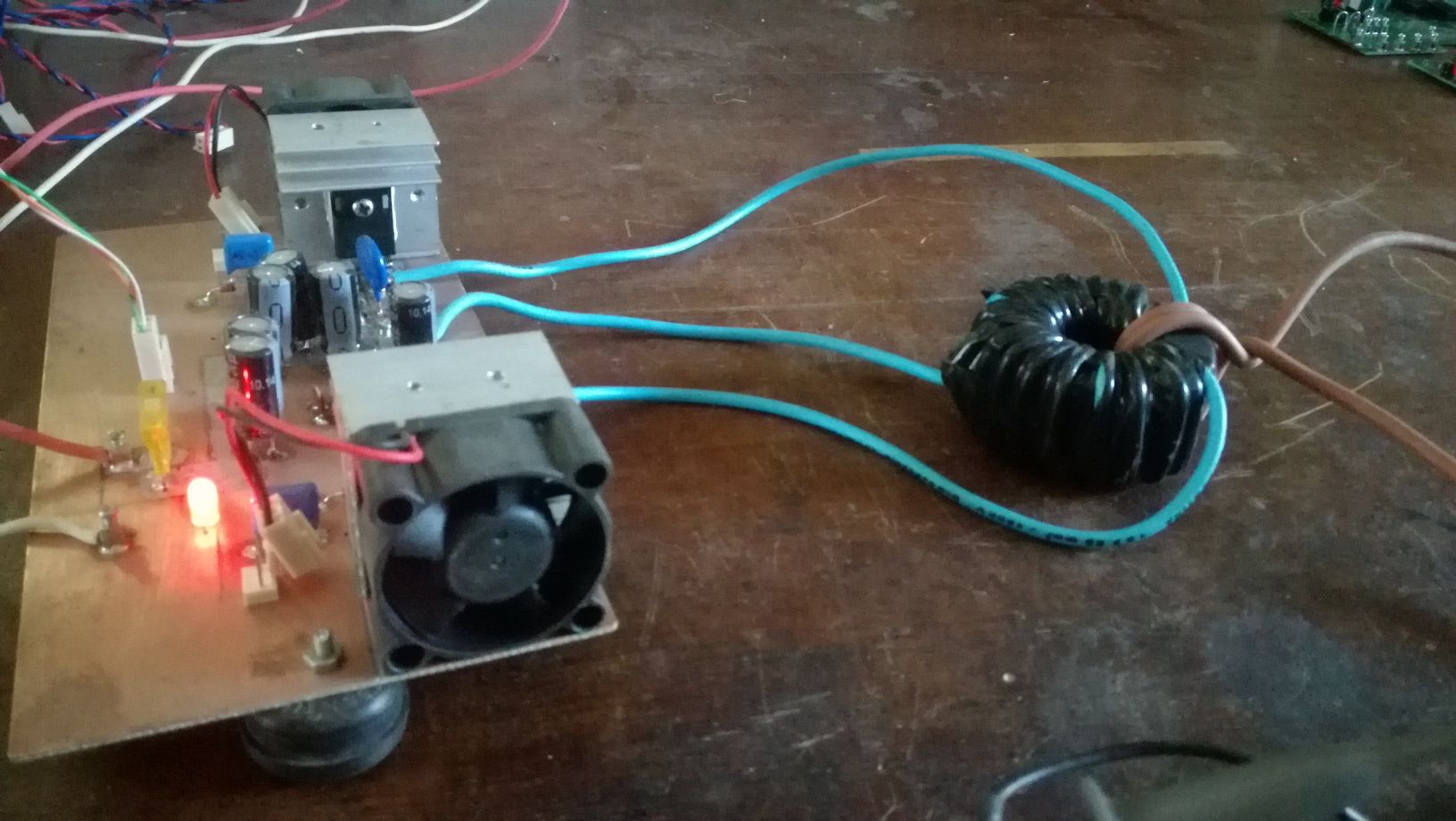
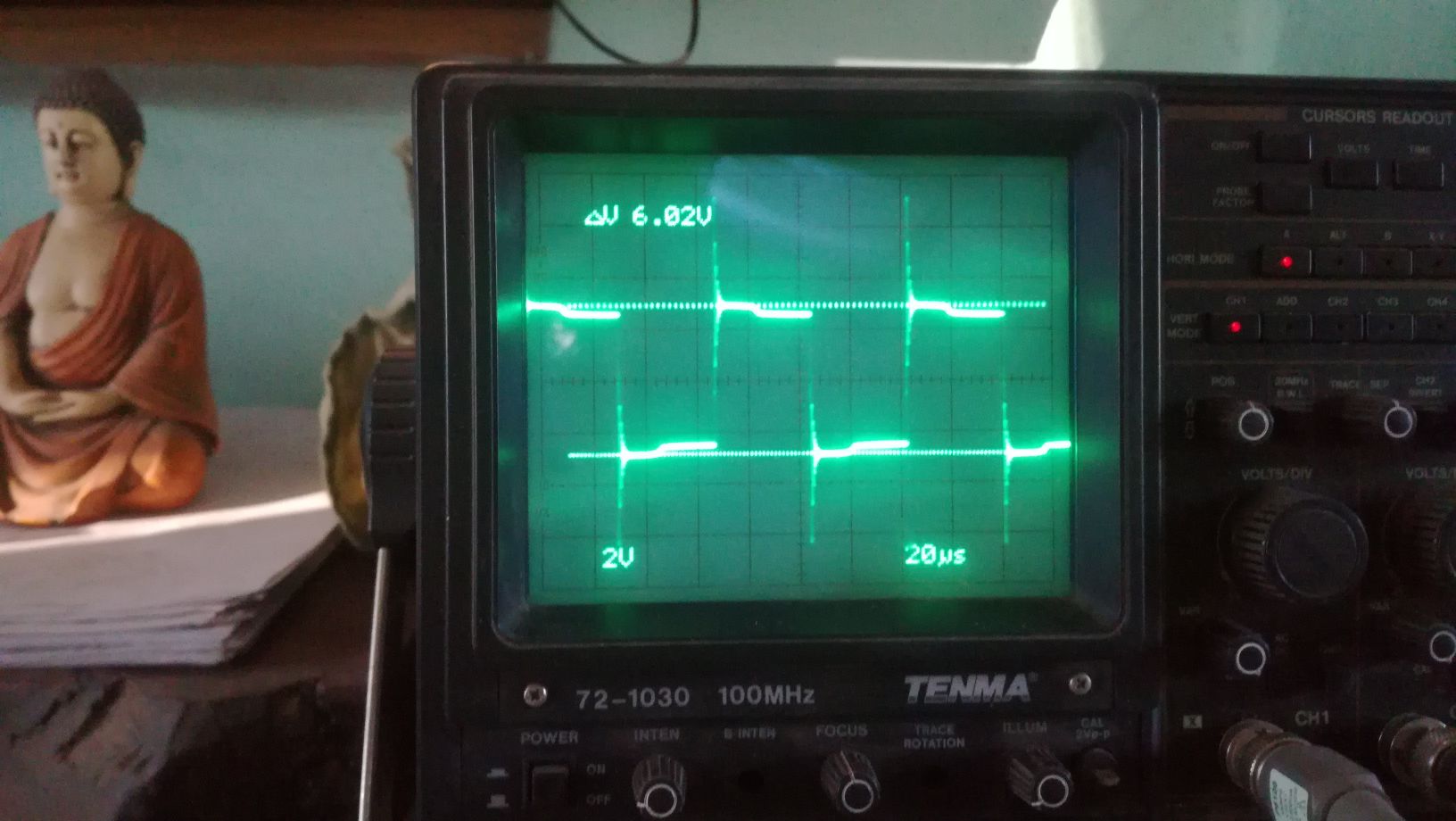
The First Part of the device we will cover is the push-pull converter. It's function is pumping charges, an analogy would be the electron-gun in the CRT, it is the source of charges. There is no magic in this part, it is just common EM technology, there are different topologies which could be used, half or full bridge would be suitable. For low frequency devices like the Kapagen also an of the shelf silicone steel transformer could be used. It is important that the output is AC. In the research we will stick to the push-pull topology for the ease of switching the two low side IGBT's. Here some images from testing this stage:

As I have time ,Ill continue to upload content and updates or corrections.

Vidura

Vidura posted this 10 December 2022

Replying To: Itsu

If you already have built the circuit, it is OK, it only needs some patience for the correct adjustment of the inductance of the CT. and as the mosfet works in the linear region near the transitions, a good heatsink is recomended. For the improoved version I might open a thread in the hardware-section, explaining a bit how it works and how the designimproovements have been developed. This will be of more benefit for others, and avoid that the circuit will be just be copied without an insight how it works.

Vidura

Aliengrey posted this 12 December 2022

Hi Vidura 

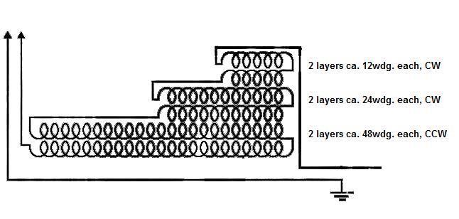
Thanks for your reply regarding the grenade winding I notice the the winding is actuly 3 windings (as per devision by 3)

 also notice in the one video the windings apear to contradict this in aperance leving the viewer (my self) a bit confused 

in that the bifilar winding is the same length as the single  winding.

Is it possible for you to show how grenade is actuly wound as i am very interested how to replicate this item as many others will also be Thinking about it, it might be a simple mater of just adding the wave length as a fraction on each winding section if thyats possible .

many thanks & Kind regards Sil

Vidura posted this 12 December 2022


Hi Sil,

In the tests shown on the videos I tried to simplify and investigate the PRINCIPALS, as only by knowing these, a reliable replication by anyone skilled in the art will be possible. These tests where intended to find the interaction of the scalar waves with the main resonator, and have demonstrated the influence of feeding the impulses on different sections, and also the correct location for the ground connection. Still I don’t know if the other principle involved, which is the atomic EXCITATION of the conductor and transfer of the former to achieve the required phase shift can be done with this simplified coil. Next experiments will show this.

Regarding the grenade coil,   it has be confirmed by different  sources, that the following schematic is correct:

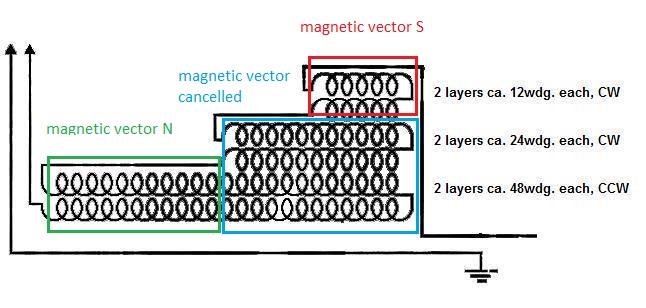
 It is important to know, that the Grenade used as main resonator, has to be in LCR resonance, in contrast to the Kacher-resonator. This means that the predominant parameter is the INDUCTANCE, not the length of the wire.

This means that the grenade has 3 sections, as you stated correctly. But these three sections has to be seen magnetically, not physically. I will mark it in the following schematic:

It is likely, that this is not the only possible layout of the main resonator, hopefully the next set of experiments will shed more light on this. By the way, just a moment ago a file which contained all the images from the BTG research has suddenly disappeared from the computer, it seems that somebody hacked in, if it'snot a technical issue.

Vidura

Fighter posted this 12 December 2022

Quoting:Vidura

By the way, just a moment ago a file which contained all the images from the BTG research has suddenly disappeared from the computer, it seems that somebody hacked in, if it'snot a technical issue.

Do you mean your computer was hacked ? You should investigate what happened. And keep backups of your research files on separate removable disk or USB sticks.

Run some free antivirus and antimalware on your computer, they should detect suspect things on your computer.

Try with Malwarebytes.

Fighter

"If you want to find the secrets of the universe, think in terms of energy, frequency and vibration."
Nikola Tesla
Vidura posted this 13 December 2022

Replying To: Fighter

Thanks Fighter, I will follow your advice.

Vidura

Jagau posted this 13 December 2022

Sorry to hear that Vidura, I'm using an old computer that doesn't have WIFI or internet connection, as a backup.
I'm not sure that a USB key is safe (malware) so that's the way I use for backup. I am not at all an expert as a fighter in this field.
Jagau

Atti posted this 13 December 2022

Vidura.

Unfortunately, I know of such a case. In the past, I would not have thought of this, I accepted it with doubt.
About a year after I first joined the previous forum, I also had the same problem with the virus. So if you can, find the "visitor" and identify it. If you can, consult an IT specialist.

Atti.


Aliengrey posted this 13 December 2022

Vidura

Thanks for the coil info it looks a bit like the Stalker device except he had it tuned to a different frequency I notice yours is tuned to 432 which is an interesting difference.

Hi to all

Yeah; malware bytes are good I used them for a good wile, there is also 'AVG antivirus' that will find and neutralise that nasty virus that targets JPeg picture files, AVG runs all the time looking for and warning of bad sites and scans any plug in

SD card Stick or Hard drive. There is also 'CCleaner' but some of the older versions Have more facilities for wiping unused parts of a disk, a smaller disk size is easier To maintain.

The other thing is if some guys have no protection they wont know the damage they do.

Sil

Munny posted this 14 December 2022

Question I had with this device where I never got what I would qualify as a satisfactory answer was the 1-to-100 frequency modulation.  Why does the high voltage have to be exactly 100 times higher frequency than the high current from the push-pull?

I understand hetrodyning but I (so far) cannot see any relationship and the 100 factor seems arbitrary to me.

Does anyone really know?  Did Akula explain this someplace and I didn't pick up on it?

If we flip frequency into bandwidth does this 100 factor now make more sense relative to the wire lengths involved?

Does it have something to do with velocity factor of the insulated wires?

Sure wish somebody could give me a definitive answer because I would think the answer embeds the foundation of how this device really operates, which to me still seems like some kind of magical mixing of high voltage/low current with high current/low voltage to end up with moderate voltage/moderate current that is usable.


Aliengrey posted this 14 December 2022

Quoting:Munny

Question I had with this device where I never got what I would qualify as a satisfactory answer was the 1-to-100 frequency modulation.  Why does the high voltage have to be exactly 100 times higher frequency than the high current from the push-pull?

I understand hetrodyning but I (so far) cannot see any relationship and the 100 factor seems arbitrary to me.

Does anyone really know?  Did Akula explain this someplace and I didn't pick up on it?

If we flip frequency into bandwidth does this 100 factor now make more sense relative to the wire lengths involved?

Does it have something to do with velocity factor of the insulated wires?

Sure wish somebody could give me a definitive answer because I would think the answer embeds the foundation of how this device really operates, which to me still seems like some kind of magical mixing of high voltage/low current with high current/low voltage to end up with moderate voltage/moderate current that is usable.

Hi Munny

if the start freq is 1.8 mhz and the wave length is 4166.6  and it's divided int blocks of  3 where do you get 100 ?

Sil


Close