BTG research

  • 5.1K Views
  • Last Post 07 January 2023
Vidura posted this 03 August 2022

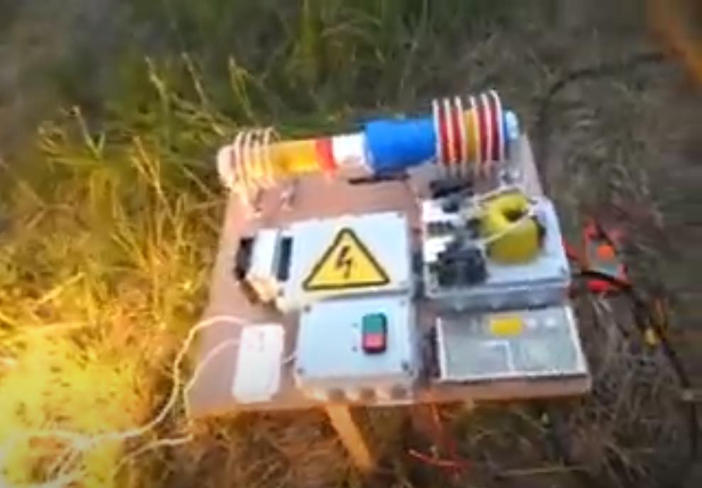
Hello Friends, I will import this thread; from the backup forum to the public category ,it is dedicated to the BTG devices like the ones shown by Ruslan and Akula. The Goal is to gain knowledge about the involved principals, and hopefully to achieve a working, self-feeding machine. Regarding the tier2 category , I want you to know that I was really tented to post for general public, and certainly the thread will be moved in the replications category when the time is right. But I also know that various persons got in serious troubles , and likely a young man lost his live, because this is the kind of devices produced in series would sensibly cut in the profits of the big energy companies.

We will in a first step go in diakoptik manner thru the different parts of the device and make different kinds of experiments and tests to get basic understanding of how this devices are working, and the interaction of the different parts. Also we will collect information from various sources from the original Builders. I would encourage those of you , who are interested in following or participating in this project, to read the thread about longitudinal waves , as this describes one of the  basic physical principals involved in this device.

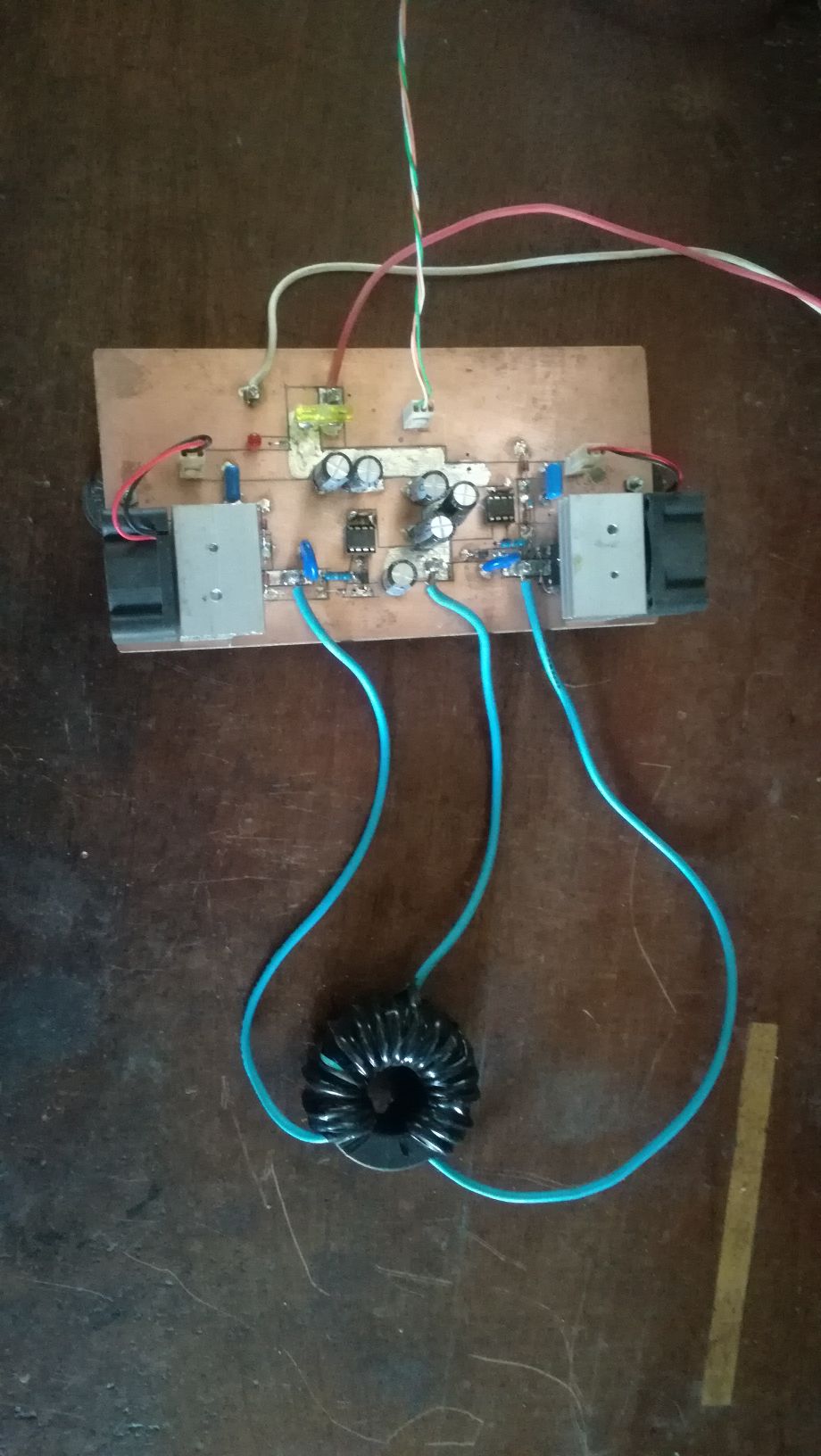
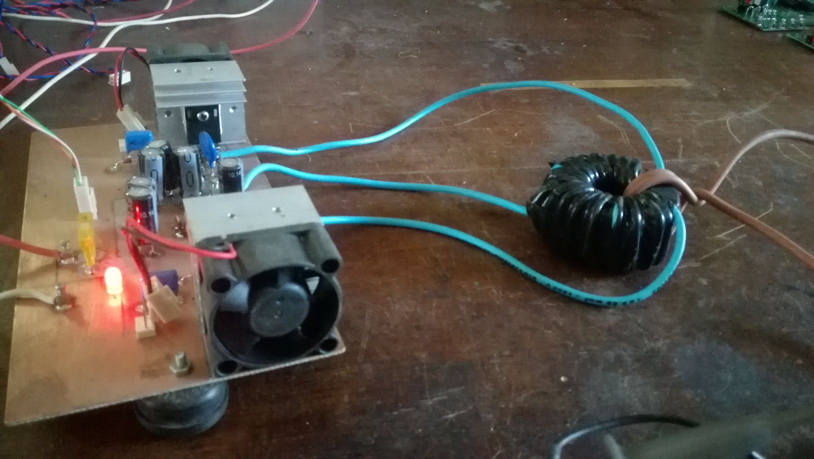
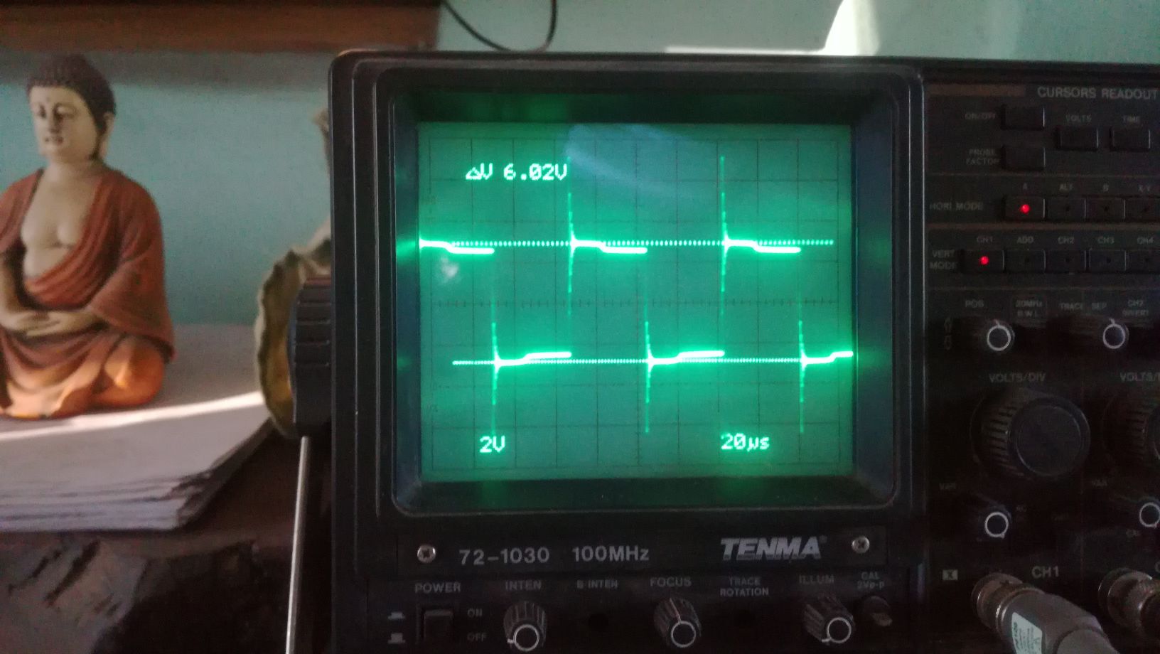
The First Part of the device we will cover is the push-pull converter. It's function is pumping charges, an analogy would be the electron-gun in the CRT, it is the source of charges. There is no magic in this part, it is just common EM technology, there are different topologies which could be used, half or full bridge would be suitable. For low frequency devices like the Kapagen also an of the shelf silicone steel transformer could be used. It is important that the output is AC. In the research we will stick to the push-pull topology for the ease of switching the two low side IGBT's. Here some images from testing this stage:

As I have time ,Ill continue to upload content and updates or corrections.

Vidura

Fighter posted this 23 December 2022

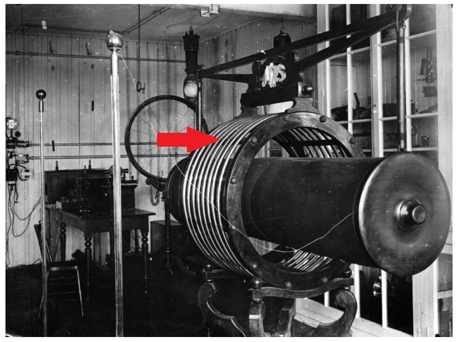
Just for inpiration.

Does it look familiar ? See the outer coils placed at distance ?

This is not an ordinary device and clearly it's not built like the transformers we know today.

It's built by Nikola Tesla and looks like this is the kind of device which inspired Kapanadze and Akula when they built their devices.

Unfortunately we can't see the coils inside the metal cylinder but they're there, see the wire going inside the cylinder.

Regards,

Fighter

"If you want to find the secrets of the universe, think in terms of energy, frequency and vibration."
Nikola Tesla
bigmotherwhale posted this 24 December 2022

Quoting:Vidura

Replying To: Aliengrey

Yes we need the standing wave in the TC, as E-field generator, it was there in the last tests, but not properly received or converted in the main or output coils.

In my opinion, The standing wave should be in the opposing coils and the TC should have a unipolar pulse that acts a dc bias. 

Aliengrey posted this 24 December 2022

Vidora Hi

What I need to ask you is what is the wave length of your TC  to find this you need an Os'Scope and a Gig gen and you need to find where the second  node is at the end of the winding,  make sure there are no other active nodes  the note that frequency.

WHAT IS IT ?


regards Sil

Vidura posted this 24 December 2022

Quoting:Fighter

Just for inpiration.

Does it look familiar ? See the outer coils placed at distance ?

This is not an ordinary device and clearly it's not built like the transformers we know today.

It's built by Nikola Tesla and looks like this is the kind of device which inspired Kapanadze and Akula when they built their devices.

Unfortunately we can't see the coils inside the metal cylinder but they're there, see the wire going inside the cylinder.

Regards,

Fighter

Nice coil😄

Tesla used this kind of resonators (free oscillating coils) to produce dampened waves, as kapa, ruslan ,akula did later.

There is a document of an interview with Tesla and an agent of the patent office, where he explained the purpose of the dampened waves, resuming he states that if the energy is directed prevailing to the ground , it can be totally recovered, but if it is irradiated it is lost. The enclosure could be a container for oil, which prevents streamers.

Vidura

Vidura posted this 24 December 2022

Quoting:bigmotherwhale

Quoting:Vidura

Replying To: Aliengrey

Yes we need the standing wave in the TC, as E-field generator, it was there in the last tests, but not properly received or converted in the main or output coils.

In my opinion, The standing wave should be in the opposing coils and the TC should have a unipolar pulse that acts a dc bias. 

Of course, there is also a standing wave in the reception coil, as it is in resonance, but with the push-pull it wont have sufficient potential to lite a neon nearby, this only happens when the scalar wave from the HV source is properly received. Have you managed to get a unipolar pulse from a TC?

Vidura

Vidura posted this 24 December 2022

Quoting:Aliengrey

Vidora Hi

What I need to ask you is what is the wave length of your TC  to find this you need an Os'Scope and a Gig gen and you need to find where the second  node is at the end of the winding,  make sure there are no other active nodes  the note that frequency.

WHAT IS IT ?


regards Sil

When I have time I'll do the measurement. But note that the kacher is selftuning, it will always oscillate as 1/4 wave resonator, but the wavelenght depends on the parameters of capacitance, thus it changes when the antena is connected, or the receiving coil mounted. Also the ground wire has some influence.

Vidura

Aliengrey posted this 24 December 2022

Quoting:Vidura

Quoting:bigmotherwhale

Quoting:Vidura

Replying To: Aliengrey

Yes we need the standing wave in the TC, as E-field generator, it was there in the last tests, but not properly received or converted in the main or output coils.

In my opinion, The standing wave should be in the opposing coils and the TC should have a unipolar pulse that acts a dc bias. 

Of course, there is also a standing wave in the reception coil, as it is in resonance, but with the push-pull it wont have sufficient potential to lite a neon nearby, this only happens when the scalar wave from the HV source is properly received. Have you managed to get a unipolar pulse from a TC?


Aliengrey posted this 24 December 2022

Yes unipolar pulse is a pulse going one way posative or negative but one and not the other as that would be a bipolar pulse,  my wave length is 1.5Mhz so to get another node at 3Mhz i have to retune my SG to that frequency and all i get is a sine wave and uless its got to be driven by a square wave I get nothing

Have you any idears ??


Sil

Vidura posted this 24 December 2022

Replying To: Aliengrey

Any coil or peace of wire has its own resonant frequency, and will always vibrate in the same, or any harmonic of it. Regardless how it is excited it will vibrate according a sinusoidal law. If you hit a bell you can't expect wind coming out, only sound . The most similar output to a unidirectional pulse would be produced by a nanopulser, and even here we could expect the dampened wave from the coax cable, although in the 100mhz range for a short length of one meter approximately.

Vidura

Vidura posted this 24 December 2022

A short update. As the latest tests didn't result as expected, I went a step back and tried the transfer without the push-pull stage, and found the problem there. It seems that the earlier assumption of related wirelenght was correct, with the two actual receiving coils I couldn't get not nearly a good result as in the earlier experiments with wavelength relationship. So I will have to get more wire and rewind the coils to confirm that.

Vidura

Close