Editor's ZPM replication

  • 4.3K Views
  • Last Post 29 June 2023
editor posted this 07 November 2022

Hello All!

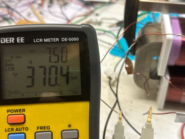
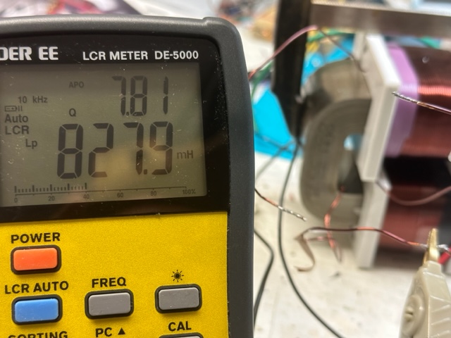
I was in touch with the Fighter and now I decide to show what is going on and to get some new ideas on how to get the signal that we all expect. Below is a quick video showing the simple setup. The coils are 1mm L1 cw 210T (370mH), L2 280T ( 828mH). 


The poles were tested with the phone app named Pole detector, works ok.

I have built some other coils too, with different turn numbers but the output was almost the same.

I have 2 different grounds to play with. I did use the regular power supply but my home appliances were not happy at all, so I decided to isolate everything.

For sure there are differences from Fighter setup, like the core, the position of the coils, the voltage, not sure about the ground.

the video:😁


bre


Itsu posted this 07 December 2022

Editor,


thanks for the additional info, the link does not work properly, so i cannot find your specific vice, but i see what you mean.

Also a nice app for counting turns πŸ‘

Itsu


Fighter posted this 07 December 2022

Hi,

I fixed the link.

Sorry, the server code is interpreting ":" + "3" put together as an emoticon.

Regards,

Fighter

"If you want to find the secrets of the universe, think in terms of energy, frequency and vibration."
Nikola Tesla
editor posted this 16 December 2022

Hi all, 


Nothing special to share, but just to let you know that I'm still in the loop.

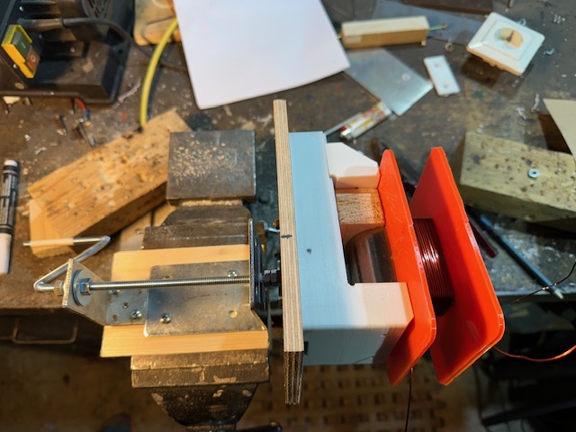
Finish printing all the parts with PETG and start to wind the first coil. Hope to finish the

coils this weekend.


Have a nice day or night, e


editor posted this 18 December 2022

Hi all!

I ran out of copper again.😊 The new one is already ordered and I hope to get it before the holidays.πŸ₯³

Reading about the formulas and calculating lately on the forum, for me, is a bit of a waste of time. We don't need formulas at all, just a selfrunning machine, that's it. It is still not presented, but we are aiming for that goal, I hope. Then we can calculate and argue as much as we want. This is just my humble opinion.The only USEFULL COP device for me is selfrunning, and that's it.


have a good day or night, e

Fighter posted this 18 December 2022

Quoting:editor

We don't need formulas at all, just a selfrunning machine, that's it. It is still not presented, but we are aiming for that goal, I hope. Then we can calculate and argue as much as we want. This is just my humble opinion.The only USEFULL COP device for me is selfrunning, and that's it.

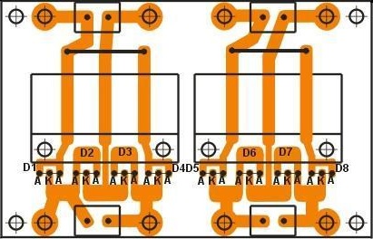
I agree, that is the ideal scenario where this kind of calculations will simply not be necessay anymore. But that's still a goal, last time when I tried to rectify ZPM's output it destroyed the capacitor on one of my custom made bridge-rectifier channels:

This is the basic schema which was modified/adapted for the different layout shown in the image above:

Seems the MBR4045PT high-frequency Schottky diodes were not able to handle the high-frequency and high-voltage negative pulses (sometimes going up to 180-220V) on ZPM's output and these pulses reached the electrolytic capacitor. It did get very hot within about half of minute and its top got deformed. So it was gone, I'm not sure if all the diodes are still functional, didn't verified them since then.

So yes, there is still a lot of work to do on ZPM's output rectification. Probably I'll need to rebuild this bridge-rectifier using much faster components with much higher voltage.

Regards,

Fighter

"If you want to find the secrets of the universe, think in terms of energy, frequency and vibration."
Nikola Tesla
Munny posted this 20 December 2022

We may need to use a lamp in series with rectification so the power has somewhere to go while we work out the best method for rectification.  Just take it a step at a time until we can shunt the lamp and run without ejecting the innards of the components.

We also need to setup the closed-loop framework and have that in place so when we finally get it dialed in, the system takes off on its own and we can yank the power supply cord for good.  There's a possibility an interim step will be necessary where we do double conversion.  Hopefully not, but best to plan for it during optimization.  Until we know all the factors that govern the ZPM performance, keep every option on the table.  My gut feeling is we have a situation where the ZPM sits in the middle of a transmission line and each end of the line must have the proper impedance or the ZPM simply can't do what we know it's capable of.

editor posted this 21 December 2022

Hi Munny!


I agree with the impedance comment. Well see. Got a few kg of copper today from a friend, so I will try to continue as soon as possible. Just have to print another part for the former, because I was too strong... Then the goal is to get the effect, find the resonance like in one of the Fighter's video.


br, e

editor posted this 27 December 2022

Hi All!


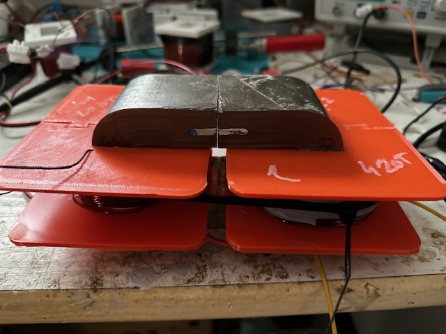
some little progress in the last days, but i finally manage to put it together, 200-420T ration.

Just have to connect everything and wait for the xmass lightsπŸ˜€.


editor posted this 30 December 2022

Hi All!

another try but currently no luck. I'm using the commercial 5A PS with no ground with an isolated transformer. The scope is grounded, the ordinary FG and IRF 250 or 460, no gate driver.

The core is amcc320 from Mouser, wire 1mm.
The coils are 200T, with 185mH ( 1Khz ), the big coil was 420T and 900mH. The turn radio was very close to 1:2. No effect. Then I unwind the bigger coil -20T ( 850mH), another -22T ( 760mH)
and another -20T (680mH), no difference at all.

The coils are connected in the proper way N-N on the top. wind cw-cww.

I'm thinking that there is something wrong with my core.
Also I tried different loads to get higher or lower impedance regarding the coils but the device works just like a light dimmer.

Very bright at lets say 1khz till 30khz ( dimming)  and the more dimming effect is increasing till no light. I can't get the way that Fighter has shown in his video (finding the resonance)

Then I add the UF4007 to the light, changing polarities...

on the load:

Any thoughts?

Really wish that Atti will manage to get it working with his new core.  πŸ˜


Have a nice day or night, e

cd_sharp posted this 30 December 2022

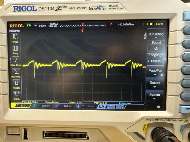
Hi, Editor, the negative terminal of your PS needs to be grounded. Otherwise, the device resonates at a very high frequency, which is not good for the Metglas core. This is visible on the scope shot you posted. The trace looks correct, but you need to bring down the resonance frequency.

I think you can feed your scope using the isolation transformer, instead. You will see the benefits of a cleaner trace and no risk of burning the scope. Stay strong!

If you know how to build such a device and you're not sharing, you're a schmuck! - Graham Gunderson

Close