
I transferred my thread on Ferrite at Work here to BeyondUnity.org
What we consider to be empty space is merely a manifestation of unawakened matter. N.T.
I transferred my thread on Ferrite at Work here to BeyondUnity.org
What we consider to be empty space is merely a manifestation of unawakened matter. N.T.
I think we use the same ferrite Lostfox.
The one I have is the Ferroxicube 3E27 epoxy coated
Magnetic permeability of 6000 and with that everything has been working wonderfully for 14 days and yes 2 weeks now. The tension does not drop and I am as you say fascinated by this circuit which requires that to be studied. I have several theories now and plan to talk to you soon.
After 14 days Losfox I think we have a real selfrunner in our labs, what do you think?
Jagau
What we consider to be empty space is merely a manifestation of unawakened matter. N.T.
Another drawing made by Rakarskiy all in colors which could help to make the circuit of Nekvadrat.
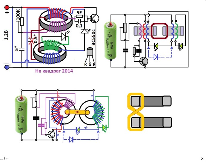
To note on the base of the transistor the capacitor 0.1uf in parallel with the resistance of 5 ohms, probably to give more stability to the circuit, therefore to try.
jagau
What we consider to be empty space is merely a manifestation of unawakened matter. N.T.
Nice drawings Jagau !
I don't remember their type but they are not ceramic type, they have plastic cup on outside and nanocrystal tape inside. Their permeability as far as I remember was from 40.000 to 70.000. But yes the best core material will be more productive here.
It indeed looks to be a self runner! I will try to run it with 12v using 3 li-ion batteries 18650 - 3400mAh each. So the changes should be the transistor to be high power one and maybe a resistor 100 ohm 1-2w resistor in series with the potentiometer may also required. Also 3-4 Leds in series will substitute the single ones. Mosfets and IGBTs also need to be tested.
Rakarskiy (user name added by Fighter):
Доброго здоровья всем! Я добавлю немного материала по схеме "не квадрат"! У меня есть собственное видение того, как работает эта схема. В любой энергетической отрасли важным моментом является индукция. Феррит не имеет хороших показателей. Сердечник должен быть выполнен с хорошими показателями инерции и индукции поля. В этом случае добавьте диод в противоположном направлении к светодиоду. Но самое лучшее решение-рассчитать схему по параметрам.
Translation (added by Fighter):
Good health to everyone! I'll add some Nekvadrat material! I have my own vision of how this scheme works. In any energy industry, induction is an important consideration. Ferrite does not perform well. The core must be made with good inertia and field induction. In this case, add a diode in the opposite direction to the LED. But the best solution is to calculate the circuit according to the parameters.
Исходя из логики, я упростил схему, но в этом варианте нужно более корректно подходить к расчету схем, лучше делать это на железном сердечнике.
Translation (added by Fighter):
Based on logic, I simplified the circuit, but in this version you need to take a more correct approach to calculating the circuits; it is better to do this on an iron core.
Yes lostfox a great challenge to take up in 12 volts to be followed with interest.
And also welcome to the thread, rakarskiy and thanks for being there too to give some good advice.
Here we are only at the beginning of the experiment and you have a lot of lead over us on the Nedbvadrat circuit.
Many members here are interested in knowing it better and I believe in developing it.
As for the different calculations to be done, fortunately today on the net there is a lot of availability which can save us a lot of time.
When you have time, I would like to read your theory on this circuit and I believe that it will interest several.
Question:
when you say:
The core must be made with good indicators of field inertia and induction
Is it related to the magnetic permeability ? Maybe with Metglass it will be better than ferrite?
have a nice day
Jagau
What we consider to be empty space is merely a manifestation of unawakened matter. N.T.
Rakarskiy (user name added by Fighter):
magnetic permeability for cores has two levels, absolute and permeability. The relative permeability indicates how many times the magnetic flux in the core has increased compared to the magnetic permeability of the vacuum. If we have a solenoid with a length of 30 mm (0.03 meters) without a core, with a certain number of turns (100), then when it is closed into an electric circuit with a current of 1 ampere, we get the magnetic field strength, which is calculated by the formula (Н = I * w/ L).
H(Am) = 1 * 100/0.03 = 3333 Am (Ampere per meter) ; To find out the magnetic induction of this field in Tesla, it is enough to use the relation (1Am = 1, 256 х 10 (-6) Т). 3333 Am * 0,000001256 = 0,004186248 T
Usually, unclosed ferrite has a relative permeability of 600: 600 * 0,004186248 = 2,5 T.
Unfortunately, we will not get this value in reality. The reason is in the limiting possibilities for material saturation, for ferrite it is within 0.5 T.
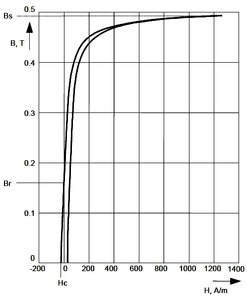
In fact, with this value of the strength of the electromagnetic field, we will heat up our core. There is one more feature that, in our opinion, is not related to field radiation, the value at the end of the core pole will already be in the region of 1/2 of the real saturation. Steel has a maximum saturation field of up to 2T compared to 0.5T ferite. In addition, electrical steel can withstand high values of the strength of the original electromagnetic field. Academic sources indicate that the frequency limit for steel is around 5 kHz. But this requires very thin sheets.
Rakarskiy welcome and thanks for sharing!
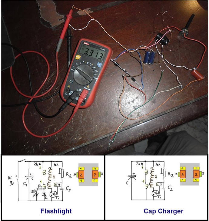
I tried your circuit. But its charging the capacitor (5.4V - 5F) only if I remove R1 with led and place a simple diode there. Actually the two diodes have no perpuse to be there at all..
With the LED in circuit, the Cap is discharging slowly. I put more turns just to fill up the gap.. turns was 80- 160 -80.
Hello Rakarskiy
Good discussion;
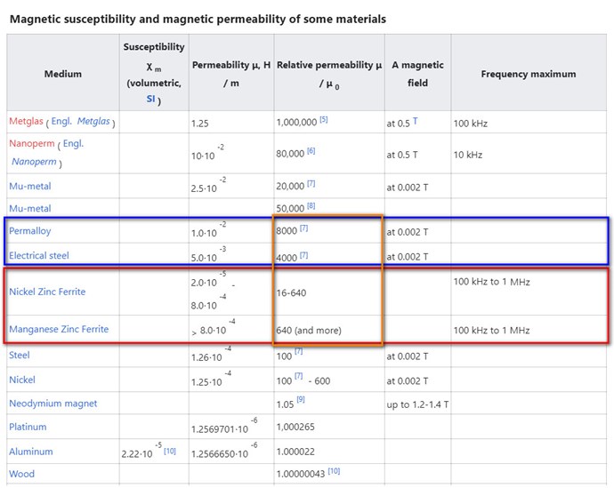
This is a theory that seems valid I think but I think it could probably only be used to increase power with a different circuit than this one. The fact of using iron as a material greatly decreases the magnetic susceptibility which in my opinion has a very great importance that must be taken into consideration with this small circuit.
The ease with which the ferromagnetic material becomes magnetized (susceptibility) with very high inductance factor of 6000 and for these 3E25 ferroxcube allows this circuit to operate at low power . At the moment iron does not have this possibility
so with a very very very low current I can make these ferrites oscillate with a saturation well below the data sheets
Probably Nekvadrat who is the author of this circuit could add some.
Don't worry, this is just the start of my theory, we still have a lot to say.
Jagau
What we consider to be empty space is merely a manifestation of unawakened matter. N.T.
Hi LOstfox
Nice demonstration, you are now the inventor of a new circuit to charge a capacitors, you are amazing
Thanks for sharing
Jagau
What we consider to be empty space is merely a manifestation of unawakened matter. N.T.
Rakarskiy (user name added by Fighter):
Now take it and wind it a little differently. "Dumbbell winding" should be performed with a larger cross-section, but with fewer revolutions. Then the led and resistor will be justified. The reverse stroke that this winding performs must have a lower resistance and a length sufficient for the self - induction EMF to be dimensionally greater than the battery or source voltage by 1.618- 2 times. then the condition of the charge current pulse according to the Ohm's law is fulfilled.In General, this scheme was planned to compensate for the battery charge, but it is too simple.The development is already a commercial project, but the solution was suggested by a Nekvadrat scheme.
The formula for the maximum current pulse calculation according to Ohm's law is the same as for a traditional generator:
Current (Ampere) = Self-induction EMF (volts) - Battery charging voltage (volts) / dumbbell winding resistance (Ohms) + battery resistance (Ohms) + diode resistance (Ohms)
The charge pulse will be, not increasing, but decreasing. The current will only be up to the EMF = battery voltage level
*****
link to the stimulation process. I recommend taking a simple digital generator. Unfortunately, the simulator can't calculate the actual field. But the chain's algorithm works fine. I used the capacitor to simulate the discharge of the source. In this version,there is a discharge, but this is natural, taking into account the primary and secondary parameters.

No one online at the moment

