
I transferred my thread on Ferrite at Work here to BeyondUnity.org
What we consider to be empty space is merely a manifestation of unawakened matter. N.T.
I transferred my thread on Ferrite at Work here to BeyondUnity.org
What we consider to be empty space is merely a manifestation of unawakened matter. N.T.
Hi all
Another important detail:
Whether it is for this project or another, never let your DDM constantly connect to your circuit.
Why; the DDM has impedance and it eats the battery slowly, rather randomly taking time-to-time tests.
The input impedance of my DDM is 10 meghom, some lDDM have a lower impedance going up to 1 megohm, check this when you buy a DDM.
Here in this project we use low voltage.
P.S. On a microwave oven there is a parallel resistance of 10meg. on the capacitor, it is used to discharge the capacitor when the microwave is stopped.
Jagau
What we consider to be empty space is merely a manifestation of unawakened matter. N.T.
Hi.
Jagau.
I used a non-self-oscillating oscillator to investigate why you can recharge the battery. Currently this is my opinion .You can also watch in the video.If my time allows, I will try another layout later.
Hi Atti
You are correct, indeed experiment with various options that's how we move forward.
thank you for sharing your research.
@all
Do not try to recharge ordinary batteries, it will not work. Only rechargeable ones work and specifically NI-MH types
Jagau
What we consider to be empty space is merely a manifestation of unawakened matter. N.T.
Hello team,
special thanks to Nekvadrat.
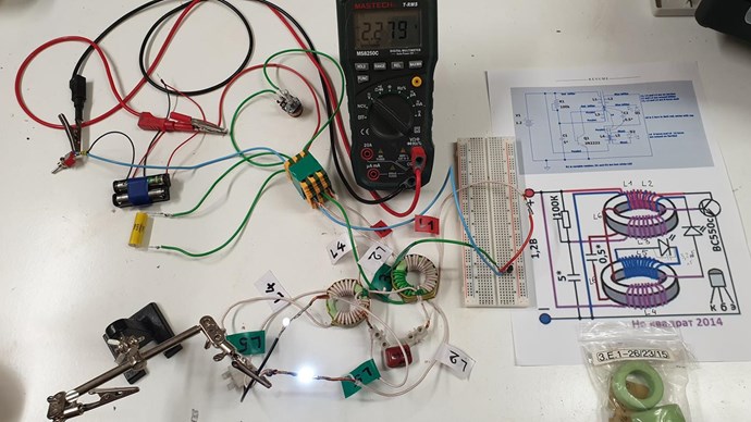
here is my setup (with the materials I had on hand):
- 2 ferrites dimensions: 36 X 22 X 15 mm (unknown material - old stock);
- 1 capacitor 2,2uF 250 V (C1) unpolarized, reference A50IT42202660K;
- 1 capacitor 0,66 uF (C2) unpolarized;
- 1 capacitor 3,2nF HT unpolarized (added in parallel with D2 for more luminosity on D1);
- 1 NPN 30 V transistor, 120 mHz, 2 A;
- L1, L2, L4, L5 and L6: Litz wire 0.1 mm X 180 strands;
- L3: 0.2mm x 19 strands tinned copper, stranded wire;
- R1 50 kΩ X 2 A (50 is sufficient, besides I did not have 100 k) ;
- V1: 2 AAA rechargeable batteries 1.2 V, 700mAh NiMH in series.
- I needed, as indicated above, to reverse the ends of L3.
- I secured the two loops of L6 with smalls nylon clamps.
I stopped adjusting R1 just as both leds stopped flashing.
D1 is very bright, D2 is much less.
V1 is currently stabilized at 2.280 V, after a gradual increase in voltage (starting at 2.150 V).
The circuit was powered up about 20 hours ago, so it will be necessary to monitor progress.
Hi Mimo
Very interesting, and clean setup, I note that you use litz wire
I can't wait to see the results with this type of wire.
thank you for sharing, we keep in touch.
P.S. I think we have a good team here,8 members have already tried and the results seem positive to most of you. it is certain that there will get positive results.
Jagau
What we consider to be empty space is merely a manifestation of unawakened matter. N.T.
Hi all.
Today I replicate the circuit and submit it to analysis,
This week I tell you what I have found.
Also photos, of course!
Very interesting how it works, it's a bit complicated
to explain, in fact I still don't quite understand it.
But time to time, it's just that.
YoElMiCrO.
Up and going again. Had to resort to the 3055 as I blew the 2222 about 5 mins in. Showing 9.6 mhz and 9.6v on the collector. Battery is showing a rise at this time. Will be loging the voltage every .5 hr for a while tonite to see where it goes. Using a AAA NiMh to start with. Will try and find a set of bigger. Starting volts was 1.257
thay
Welcome aboard Thaelin As you may have surely noticed, the adjustment of the 100K variable resistor is very important.
@mimo, I am curious to know if Litz's cable is behaving well?
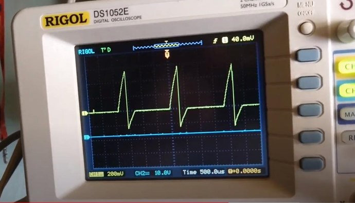
@YO, it looks like a very simple circuit but it has potential. One thing I noticed the 2 LEDs must be there.
If we remove one the circuit stops charging, as if the 2 leds act as a switch. The oscillator is easy to analyze but in the second rear BEMF of the second ferrite this is what I have not yet understood. It is as if two impulses crossed, this is what I see on the oscilloscope
Jagau
What we consider to be empty space is merely a manifestation of unawakened matter. N.T.
Nekvadrat (user name added by Fighter):
...репликации в большинстве случаев имеют положительный результат. Имеет смысл расположить тороиды определенным способом, к примеру друг над другом ...либо перпендикулярно. (могу и ошибиться, но ведь мы здесь для получения результата...)
Translation (added by Fighter):
...replications in most cases have a positive result. It makes sense to place the toroids in a certain way, for example, on top of each other...or perpendicularly. (I could be wrong, but we are here to get results...)
Nekvadrat (user name added by Fighter):
....Jagau,...многие знают "переключатель Тесла". В данном варианте Вы можете попробовать свой переключатель, - заряженных АКБ, почему нет?
Translation (added by Fighter):
....Jagau,...many people know the "Tesla switch". In this option, you can try your switch - charged batteries, why not?

No one online at the moment


